V. electrical connections, A. high-voltage connections, Figure 11 —high- & low-voltage connections – Bryant 585B User Manual
Page 7
Attention! The text in this document has been recognized automatically. To view the original document, you can use the "Original mode".
junction with all applicable criteria presented in this section of
the unit Installation Instructions.
NOTE:
The minimum installation requirements of the duct
system must be in accordance with the standards of the Na
tional Fire Protection Association for installation of air con
ditioning and ventilating systems of other than residence-
type, NFPA No. 90; or residence-type, warm-air heating and
air conditioning systems, NFPA No. 90B; and/or local codes
and ordinances.
The following criteria must be followed when selecting, siz
ing, and installing ductwork:
1. Ductwork, registers, and return-air grilles should be
selected and sized according to ASHRAE recommenda
tions and as presented in BDP training materials.
CAUTION:
When drilling duct flange fastening holes in the
unit side, use care to avoid puncturing the evaporator coil.
2. Ductwork can be screwed or bolted to unit duct flanges.
Use suitable gaskets to insure airtight seal.
3. External fleld-supplied air Alter must be installed in re-
turn-air ductwork. Recommended sizes for filters are
shown in Table I. Install filters where they are easily ac
cessible for service.
NOTE:
Accessory plenums and horizontal economizers have
factory-supplied, high-capacity filters.
4. Avoid abrupt duct size increases and reductions.
5. Provide supply and return ductwork with an approved
vibration eliminator.
6. Adequately insulate and weatherproof all ductwork
located outdoors. Ducts passing thru unconditioned
space must be insulated and covered with vapor barrier
in accordance with latest issue of SMACNA and NESCA
minimum installation standards for heating and air
conditioning systems.
7. Secure all ducts to building structure.
8. All openings in building structure must be properly
flashed, weatherproofed, and vibration-isolated in ac
cordance with local codes and good building practices.
V. ELECTRICAL CONNECTIONS
WARNING:
The unit cabinet must have an uninterrupted or
unbroken electrical ground. This can consist of electrical
wire connected to the ground lug in the control box or con
duit approved for electrical ground, when installed in ac
cordance with existing electrical codes.
CAUTION:
Copper conductor is the only type of wire that is
to be connected between the electrical disconnect and the
unit. Do not use aluminum wire.
Operation of the unit on improper line voltage, or with ex
cessive phase imbalance, constitutes abuse and is not
covered by warranty.
All electrical connections must be made in accordance with
the National Electrical Code and local electrical codes
governing such wiring.
The unit must be electrically grounded in accordance with
the National Electrical Code, ANSI CI-1975, when an exter
nal electrical source is utilized.
A separate electrical line with a fused disconnect switch
mounted at, or within sight of, the unit should be used for
this installation. Refer to the unit rating plate for maximum
fuse size. See Table II, III, or IV for recommended wire sizes
and lengths.
WARNING:
Label P/N A-74191B, which is shipped loose in
bag of parts, must be affixed to the electrical disconnect box.
This label states: “Do not disconnect the electrical power to
this appliance without first turning off the gas supply.”
NOTE:
Fused disconnect may be mounted directly on con
trol corner panel. To mount disconnect on this panel, align
disconnect box knockout with unit high-voltage inlet hole
and secure box to panel. Route wiring from disconnect
through aligned knockout and unit inlet.
CAUTION:
Ensure that the drill does not damage any com
ponents when drilling through the panel.
NOTE:
If aluminum conductor is used from the electrical
service to the disconnect switch where local codes permit the
use of aluminum wire, the connections must be made in ac
cordance with the National Electrical Code. In preparing the
wire, just before installing the connector, all aluminum wire
must be “brush-scratched” and then coated with a corrosion
inhibitor, such as Pentrox A. When it is suspected that the
connection will be exposed to moisture, it is very important
to cover the entire connection completely to prevent an
electrochemical action that will cause the connection to fail
very quickly. Reducing the effective size of the wire, such as
cutting off strands so that the wire will fit a connector, is
very poor practice. Properly sized connectors should be used.
CAUTION:
If aluminum conductors are to be used, the wire
gauge selected must have current capacity not less than the
copper wire specified and must not create a voltage drop be
tween the service panel and the unit in excess of 2% of the
unit rated voltage.
A. High-Voltage Connections
Proceed as follows to complete high-voltage connections:
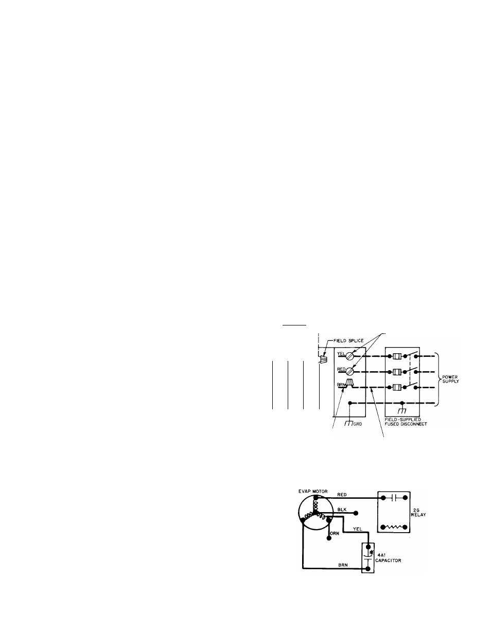
1. Run high-voltage leads from fused disconnect through
high-voltage inlet hole provided in control corner panel.
See Figure 2 for location of panel and hole.
2. Run high-voltage leads into unit control box and con
nect leads to contactor. See unit wiring label and Figure
11
.
SINGLE-STAGE HEAT a COOL-MANUAL CHANGEOVER
( p Q
THERMOSTAT P/N 344270030 {SUBBASE INCLUDED)
OR
THERMOSTAT P/N PS2758-l(OR-2) WITH
SUBBASE P/N PS2759-34
CONTACTOR TERMINALS
3
3
3
_»
llJ
>-
D
OD
Q
or
LOW-VOLTAGE PIGTAIL LEADS
CONTROL BOX
HIGH-VOLTAGE
PIGTAIL LEAD
3-PHASE
UNITS ONLY
FIELD LOW-VOLTAGE WIRING
FIELD HIGH-VOLTAGE WIRING
FACTORY LOW-VOLTAGE WIRING
FACTORY HIGH-VOLTAGE WIRING
note
: FOR AUTOCHANGEOVER
APPLICATIONS, USE THERMOSTAT
FyN 34427D52 OR PS3108A
WITH SUBBASE P/N PS3109E
note
; SET HEAT ANTICIPATOR
AT 0.85 AMPS
A76313
Figure 11 —High- & Low-Voltage Connections
A77375
Figure 12—Evaporator Motor Connections
for 208-V Operation of
Sizes 018050 & 024050
-7-