Table vim-heating service analysis chart, Ix. care and maintenance, A. air filter – Bryant 585B User Manual
Page 13
Attention! The text in this document has been recognized automatically. To view the original document, you can use the "Original mode".
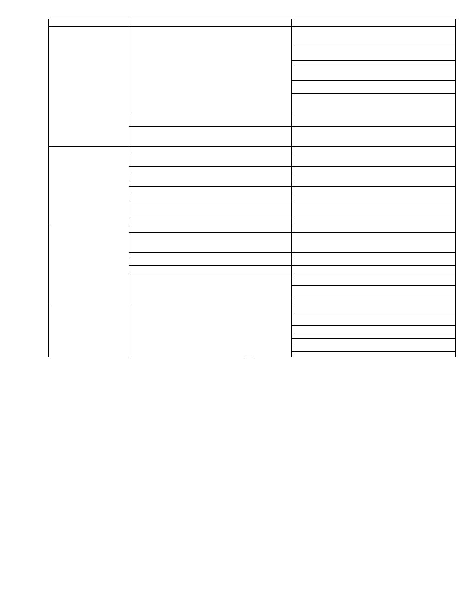
TABLE VIM-HEATING SERVICE ANALYSIS CHART
SYMPTOM
CAUSE
REMEDY
Pilot will not light.
No spark at electrode
Check air gap between electrode tip and pilot
burner. Gap should be 1/8-in. ± 1/16 in.
Readjust as necessary.
Check moisture or dirt accumulation on electrode
ceramic— clean ceramic with cloth.
Cracked ceramic— replace pilot electrode assembly.
Check for loose or broken wiring at and between
control and electrode— replace wire as necessary.
Check fuses or circuit breaker to insure voltage
to unit.
Check 24-volt input to igniter control. If
you find 24 volts and the above remedies have been
explored, replace igniter.
Spark shorting out to main burner
Realign electrode tip away from main burner
but maintain spark gap to pilot burner.
No gas at pilot burner
Check to see if pilot valve is opening. Check for
loose or broken wiring connections. If no
deficiency is found, replace gas valve.
Burners will not ignite.
W ater in gas line
Drain — install watertrap.
No powerto furnace
Check power supply, fuses, wiring, or
circuit breaker.
No 24-volt power supply to control circuit
Check transformer— replace if necessary.
Miswired or loose connections
Check all wiring and wirenut connections.
Dirty pilot— yellow flame
Clean pilot orifice.
Pilot burning properly— sharp blue flame
Replace pilot.
Burned out heat anticipator in thermostat
Replace thermostat.
No gas at main burners
Check to see if main gas valve is opening. Look
for loose or broken wiring connections. If
no deficiency is found, replace valve assembly.
Broken thermostat wire
Run continuity check to locate break.
Inadequate heating
Dirty air filter
Replace filter.
Gas input to furnace too low
Check gas pressure at manifold. Clock gas meter
for input. If too low, increase manifold
pressure, or replace with correct orifices.
Unit undersized for application
Replace with properunit— oradd additional unit.
Restricted airflow
Clean or replace filter— or remove any restriction.
. Blower speed too low
Use faster speed tap— or install optional blower.
Limit switch cycles main burners
OFF setting of fan control set too high — reset.
Dirty air filters— clean or replace.
Registers closed, restricted ductwork— open
or remove restriction.
Check heat anticipator setting on thermostat— readjust.
Poor flame characteristics
Incomplete combustion results in:
Aldehyde odors, (CO), sooting flame— floating flame
Air shutters on burners closed— adjust to soft blue flame.
Check all screws around flue outlets and burner
compartment— tighten.
LACK OF COMBUSTION AIR.
Cracked heat exchanger— replace.
Overfired furnace— reduce input, or change orifices.
Check vent for restriction— clean as required.
Check orifice to burner alignment.
2D close and complete the circuit through the compressor
motor 3F and condenser fan motor 3D1, causing both motors
to start instantly.
All motors will continue to run and the cooling cycle will re
main “on” until the room thermostat is satisfied. When the
conditioned space temperature drops to the thermostat set
ting, the electrical connection from terminal R to terminals
Y and G is opened in the thermostat. This open circuit
deenergizes the compressor contactor coil 2D and the cooling
blower relay coil 2C. The blower, condenser, and compressor
motors will stop. The cooling will remain “off” until there is
another demand for cooling by the thermostat.
IX. CARE AND MAINTENANCE
WARNING:
Never place anything combustible on or in con
tact with the unit.
Disconnect all electrical power to unit before performing
any maintenance or service on unit.
To ensure continuing high performance, and to minimize
possible equipment failure, it is essential that periodic main
tenance be performed on this equipment. Consult your local
Dealer as to the proper frequency of maintenance and the
availability of a maintenance contract.
WARNING:
As with any mechanical equipment, personal
injury can result from sharp metal edges, etc.; therefore, be
careful when removing parts.
Because of possible damage to the equipment or personal in
jury, maintenance should be performed by qualified persons
only.
The ability to properly perform maintenance on this equip
ment requires certain mechanical skills and tools. If you do
not possess these, contact your Dealer for maintenance.
The minimum maintenance that should be performed on
this equipment is as follows:
1. Check air filter each month. Clean or replace as re
quired.
2. Check cooling coil, drain pan, and condensate drain each
cooling season for cleanliness. Clean as necessary.
3. Check blower motor and wheel for cleanliness and
lubrication each heating and cooling season. Clean and
lubricate as necessary.
4. Check electrical connections for tightness and controls
for proper operation each heating and cooling season.
Service as necessary.
A. Air Filter
CAUTION:
Do not operate the unit for any period of time
without having a suitable filter in place in the return-air
duct system. Always replace filter with same size and type.
Filters are not provided as an integral part of the unit. A
filter must be used with the unit and must be inspected fre
quently. When the filter becomes clogged with dust and lint,
it should be replaced (disposable-type) or cleaned (cleanable-
type). The filter should be inspected at least once each
month, and replaced or cleaned at least twice during the
year (more often, if necessary).
-13-