A. checking components – Bryant 585B User Manual
Page 11
Attention! The text in this document has been recognized automatically. To view the original document, you can use the "Original mode".
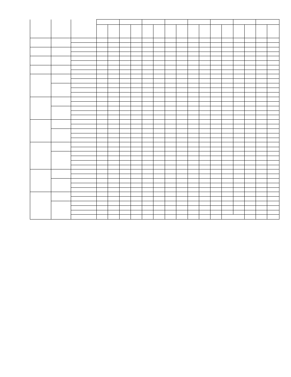
TABLE VII-AIR DELIVERY (FtVMin) AT INDICATED EXTERNAL STATIC
PRESSURE & VOLTAGE WITHOUT FILTER*
External Static Pressure—Inches wc
585B
Size
Volts-
Phase
160 Hzl
Application
Motor Speed
Settingt
0.1
0.2
0.3
0.4
0.5
0.6
0.7
0.8
208V
230V
or
460V
208V
230V
or
460V
208V
230V
or
460V
208V
230V
or
460V
208V
230V
or
460V
208V
230V
or
460V
208V
230V
or
460V
208V
230V
or
460V
018050
208-&
230-1
Heating-L
—
725
765
705
730
685
695
650
645
620
—
—
—
—
—
—
Cooling-L
—
715
745
695
715
670
670
640
615
590
_
—
—
—
—
—
024050
208-&
203-1
Heating-L
—
725
765
705
730
685
695
650
645
620
580
—
—
—
—
—
Cooling-H
—
900
930
865
885
825
840
775
780
720
710
—
—
—
—
—
024075
208-&
230-1
Heating-M
955
1030
925
1000
890
960
855
920
810
875
—
820
—
—
—
—
Cooling-L
830
910
805
885
775
855
740
820
700
780
—
730
—
—
—
—
030075
208-&
230-1
Heating-M
—
—
925
1000
890
960
855
920
810
875
765
820
—
—
—
—
Cooling-H
—
—
1165
1200
1100
1140
1045
1080
975
1010
905
930
—
—
—
—
036075
230-1
Heating-L
—
1185
—
1150
—
1125
—
1085
—
1035
—
975
—
—
—
—
Cooling-H
—
1495
—
1430
—
1360
—
1280
—
1205
—
1125
—
—
—
—
208-,
230-, or
460-3
Heating-L
—
—
1370
1410
1350
1390
1320
1360
1260
1300
1195
1230
1110
1145
1020
1050
Cooling-L+
—
—
1360
1400
1335
1375
1285
1325
1220
1260
1145
1180
—
1080
—
—
Cooling-H
1465
1510
1355
1395
1230
1265
1085
1120
036125
230-1
Heating-H
—
1640
—
1605
—
1545
—
1485
—
1425
—
1345
—
—
—
—
Cooling-L
—
1395
—
1355
—
1320
—
1275
—
1215
—
1125
—
—
—
—
208-&
230-3
Heating-Lt
—
—
1580
1630
1545
1595
1505
1550
1460
1505
1405
1450
1320
1360
1195
1230
Heating-M
—
—
1930
1990
1860
1920
1795
1850
1715
1770
1620
1670
1515
1560
1375
1420
Cooling-L
1435
1480
1370
1410
1260
1300
1115
1150
042100
230-1
Heating-L
—
1415
—
1375
—
1340
—
1295
—
1245
—
1175
—
—
—
—
Cooling-H
—
1620
—
1575
—
1515
—
1455
—
1385
—
1300
—
—
—
—
208- or
230-3
Heating-L
—
—
1600
1630
1565
1595
1520
1550
1475
1505
1420
1450
1335
1360
1205
1230
Cooling-Li
—
—
1580
1610
1540
1570
1500
1530
1450
1480
1380
1410
1275
1300
—
—
Cooling-M
1685
1720
1590
1620
1470
1500
1315
1340
048125
230-1
Heating-L
—
1460
—
1425
—
1390
—
1350
_
1305
—
—
—
—
—
_
Cooling-H
—
1760
—
1700
—
1640
—
1575
—
1490
—
—
—
—
—
—
208-,
230-, or
460-3
Heating-Lt
—
—
1600
1630
1565
1595
1520
1550
1475
1505
1420
1450
1335
1360
1205
1230
Heating-M
—
—
1950
1990
1880
1920
1815
1850
1735
1770
1635
1670
1530
1560
1390
1420
Cooling-Mt
—
—
1920
1960
1850
1885
1775
1810
1685
1720
1590
1620
1470
1500
—
—
Cooling-H
—
—
—
—
—
—
1940
_
1835
1870
1725
1760
1615
1650
1490
1520
060125
230-1
Heating-L
—
1750
—
1715
—
1675
—
1630
—
1590
—
1520
—
—
—
—
Cooling-H
—
2175
—
2110
—
2035
—
1950
—
1850
—
1735
—
—
—
—
208-,
230-, or
460-3
Heating-L
—
—
1665
1700
1610
1645
1560
1590
1490
1520
1400
1430
1315
1340
1215
1240
Cooling-Mt
—
—
2100
2145
2025
2065
1930
1970
1835
1870
1725
1760
—
—
—
—
Cooling-H
—
—
—
—
2425
2475
2330
2380
2225
2270
2090
2135
1955
1995
1820
1855
060150
230-1
Heating-M
—
2050
—
1995
—
1940
—
1870
—
1795
—
1690
_
—
—
Cooling-H
—
2175
—
2110
—
2035
—
1950
—
1850
—
1735
—
—
—
_
208-or
230-3
Heating-Lt
—
—
1665
1700
1610
1645
1560
1590
1490
1520
1400
1430
1315
1340
1215
1240
Heating-M
—
—
2155
2200
2075
2115
1990
2030
1895
1935
1795
1830
1680
1715
1570
1600
Cooling-Mt
—
—
2100
2145
2025
2065
1930
1970
1835
1870
1725
1760
—
—
—
Cooling-H
-
-
-
-
2425
2475
2330
2380
2225
2270
2090
2135
1995
1995
1820
1855
NOTE: For air delivery data applicable to size 036075 thru 060150 single-phase units with a field-installed, high-static blower, refer to the air delivery data for the
equivalent size 3-phase unit.
NOTE: 460-V units operate on the same motor speed for both heating and cooling, and are factory-set on the indicated cooling speed.
* Deduct field-supplied filter pressure drop to obtain available static pressure for ducting.
t Heating airflow values are with dry coil. Cooling airflow values are with wet coil.
iThese motor speed settings require a field wiring change. All other settings indicated are the factory setting.
— Indicates portions of the table that are beyond the recommended operating range or that are not applicable.
WARNING/DANGER:
Failure to follow these instructions
could result in serious personal injury:
1. Follow recognized safety practices and wear protective
goggles;', '7',
2. Do not operate compressor or provide any electric power
to this unit unless compressor terminal cover is in place
and secured.
3. Do not remove terminal cover until all electrical sources
have been disconnected.
4. If refrigerant leak is suspected around compressor ter
minals, relieve all pressure from system before touching
or disturbing anything inside terminal box.
System contains oil and refrigerant under pressure. Do not
use torch to remove any component. Wear your protective
goggles. To remove a component: ,
1. Shut oif electrical power to unit.
2. Relieve all pressure from system.
3. Gut connecting piping with tubing cutter.
4. Remove component from unit.
5. When necessary, unsweat remaining piping stubs
carefully. Oil may ignite when exposed to torch flame.
A. Checking Components
Perform the following steps before starting the unit.
1. Check for correct position of condenser fan blade in unit
top panel. See Figure 3.
2. Leak-test all refrigerant circuit connections to make
certain that none has been damaged in shipment.
3. Check entire system for leaks at all connections, includ
ing evaporator coil located in blower compartment. (Use
electronic leak detector, halide torch, or liquid-soap
solution.)
NOTE:
The cooling section is fully charged with refrigerant,
tested, and factory-sealed.
There should be no need to
check refrigerant charge if no leaks were found.
In rare
instances, when the refrigerant charge has been lost be
cause of a leak caused by shipping damage or a refrigerant
leak has been found, proceed as follows:
WARNING:
Never attempt to repair any soldered connec
tion while system is under pressure. Severe bodily injury
may result.
a. Locate and repair leak.
-11-