Dimensions (inches), Weight distribution, Table i-585b ratings & recommended filter sizes – Bryant 585B User Manual
Page 2: C. clearances
Attention! The text in this document has been recognized automatically. To view the original document, you can use the "Original mode".
DIMENSIONS (Inches)
Size
A
B
D
E
F
G
H
J
018050 & 024050
44-5/8
30-3/8
16
10
—
1-1/8
16
7-1/4
024075, 030075,
& 036075
44-5/8
40-3/8
19
10
_
1-3/8
13-1/4
8-7/8
036125, 042100,
& 048125
58-5/8
44-5/8
24
14
_
1-3/8
13-1/4
8-7/8
060125 & 060150
66-7/8
44-5/8
32
10
15-3/4
1-3/8
13-1/4
8-7/8
tLECTRlCAL DibCÜNNrCT
MAY BE MOUNTED ÜN
THIS PANEL
H------------------D------------------
_ 7
8
-Ft-
SUPPLY
AIR
RETURN
AIR
1
1
^ REAR VIEW
3L0W£R
ACCESS
ÜUOR
CONTROLS
ACCESS
DOOR
i!T
CONDENSER FAN
.1
?
.
TOP VIEW
A -
air
A
out
LEFT-SIDE VIEW
-IIGH-VOLTAGE
'
INLET
GAS
inlet
FRONT VIEW
WEIGHT DISTRIBUTION
A76216
Size
Shipping
Wt (Ibs)
Operating
Wt (Ibs)
Corner Wt (Ibs)
A
B
C
D
018050
325
300
77
75
73
75
024050
330
305
86
83
66
70
024075
425
395
115
110
83
87
030075
430
400
116
111
84
89
036075
440
405
117
112
85
91
036125
510
465
132
126
101
106
042100
520
475
136
129
103
107
048125
535
490
150
143
96
101
060125
600
550
142
136
132
140
060150
615
565
144
138
137
146
B
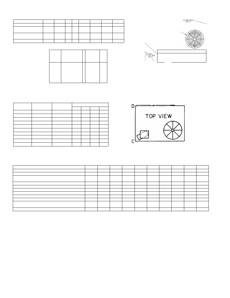
Figure 2—Model 585B Dimensional Drawing,
Shipping Weights, Operating Weights, & Weight Distribution
TABLE I-585B RATINGS & RECOMMENDED FILTER SIZES
SIZE
018050
024050
024075
030075
036075
036125
042100
048125
060125
060150
Rated Cooling Capacity (Btuh)*
18,500
23,000
24,000
29,000
37,000
35,500
42,000
47,000
59,000
59,000
Rated Cooling Airflow (Ft^/Min)*
690
850
900
1000
1200
1300
1550
1600
2200
2200
Rated,Maximum External Static Pressure
Single-Phase Units (In. wc)
0.3
0.3
0.3
0.3
0.3
0.3
0.3
0.3
0.3
0.3
Three-Phase Units (In. wc)
—
—
—
—
0.65
0.65
0.65
0.65
0.65
0.65
ARI Sound Rating Numbert
19
20
19
19
20
20
20
20
21
21
Rated Minimum Heating Input (Btuh)t
40,000
40,000
60,000
60,000
60,000
100,000
80,000
100,000
100,000
120,000
Bonnet Capacity (Btuh)
30,000
30,000
45,000
45,000
45,000
75.000
60,000
75,000
75,000
90,000
Rated Maximum Heating Input (Btuh)t
50,000
50,000
75,000
75,000
75,000
125,000
100,000
125,000
125,000
150,000
Bonnet Capacity (Btuh)
37,500
37,500
56,250
56,250
56,250
93,750
75,000
93,750
93,750
112,500
Recommended Field-Supplied Filter Size
Standard-Type (Sq In.)
288
384
384/433**
480
576
576/722**
672
768
960
960
Cleanable- or High-Capacity-Type (Sq In.)
187
250
250/281**
312
374
374/469**
437
499
624
624
*Rated in accordance with ARI Standard 210-75.
t Rated in accordance with ARI Standard 270-75.
+AII units have two A.G.A.-certified heating input ratings and are manufactured with burner orifices that permit heating operation at the minimum rating. Units
may not be derated below this minimum rating. Optional field-installed burner orifices are required to provide the optional maximum heating input rating. See
Table V.
**When size 024075 or 036125 is installed to operate at the minimum rated heating input, the recommended filter area is the smaller square inch figure shown for
each type of filter. The larger square inch figures shown are recommended when these units have been field-converted to operate at the maximum rated heating
input. All other recommended filter sizes shown in the table are determined by the cooling airflow requirements only and are not affected by the heating operation
input rating.
4 inches thick and extends 6 inches beyond the casing on all
4 sides. The slab, should be a minimum of 3 inches above
finished grade and constructed so that water runoff will not
accumulate around unit. Be sure to locate the unit where
water can not drain directly on the unit.
C. Clearances
The minimum clearance is 6 inches from the duct side, 24 in
ches from the condenser coil side, and 30 inches from the re
maining two sides of the unit to allow for adequate service
space. Minimum clearance from the top of the vent is 24 in
ches.
CAUTION:
The 24-inch side clearance stipulation assures
unrestricted airflow to the condenser fan inlet. Any restric
tion at the inlet grille can be detrimental to compressor life.
The condenser fan discharge is through the top of the unit.
When installing the unit on the ground, do not locate in a
corner or under a complete roof cover such as a carport. Min
imum clearance under a normal house roof construction is
-2-