Bryant 585B User Manual
Bryant Grills
Attention! The text in this document has been recognized automatically. To view the original document, you can use the "Original mode".
Cancels: 39585DP26-A
39585DP26-B
7/15/79
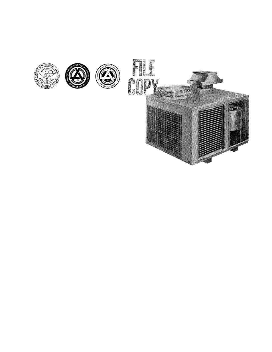
Model 585B Gas/Electric Units are fully self-contained,
single-packaged combination heating/cooling horizontal-
discharge units.
These packaged units are equipped with an energy-saving
RELITE-type electric spark ignition pilot that saves gas by
operating only when the room thermostat “calls for heat
ing.” Natural gas controls are standard. For propane opera
tion, conversion kit P/N 301625-703 must be field-installed.
Model 585B units have two A.G.A.-certified heating input
ratings. See Table I.
These units are designed for outdoor installation either on a
rooftop or at ground level on a slab. The cooling section is
factory-charged and sealed, minimizing installation time.
Installation is easy—connect gas supply, air ducts, conden
sate drain, high- and low-voltage wiring, and install the air
filter.
NOTE:
An optional condenser coil grille is available for field
installation. See Figure 1.
A full line of rooftop system accessories are available for
field installation. These accessories include plenums with
factory-supplied high-capacity filter and outside air intake
hood, unitized curbs, economizers (both downflow and
horizontal), barometric relief dampers, concentric diffuser
box assemblies, flexible duct packages, and high-capacity
filter racks with filters. When installing these accessories,
see Installation Instructions packaged with them.
fmportant—Read Before Installing
1. Check all local or other applicable codes for information
concerning proximity to property lines, height above
roof, obstructions, etc.
2. Make certain power supply available (volts, hertz, and
phase) corresponds to that specified on unit rating plate.
3. Check electrical supply provided by utility to be sure
that service capacity is sufficient to handle load imposed
by this unit.
4. Locate the unit where the vent cap is a minimum of 4
feet from openable windows or doors.
5. The installation must conform with local building codes
or, in the absence of local codes, with the National Fuel
Gas Code ANSI Z223.1.
GENERAL
The condensing section has been designed and tested in ac
cordance with ARI 210. The appliance design is certified by
American Gas Association for use with natural or propane
gases with appropriate controls and orifices.
Installation of the unit consists of the following:
I. Moving and Setting Unit In Place
II. Venting
III. Gas Piping
A77017
Figure 1—Sizes 024075, 030075, &
036075 With Optionai Condenser
Coii Griile instaiied
IV. Duct Connections
V. Electrical Connections
VI. Preparing Unit for Startup
VII. Heating Startup and Adjustments
VIII. Cooling Startup and Adjustments
IX. Care and Maintenance
I. MOVING AND SETTING UNIT IN PLACE
CAUTION:
Be sure to protect the top and sides of the unit
when rigging the unit to be lifted. See Figure 4.
Extreme caution should be used to prevent damage when
moving the unit. The unit should remain in an upright posi
tion during all rigging and moving operations. To facilitate
lifting and moving, place the unit in an adequate rope or
cable sling.
A. Rooftop Installation
Place the unit on a level base. See Figures 8 and 9 for typical
installations. On flat roofs, be sure that the unit is at least 4
inches above the roof to prevent flooding. Consult local codes
for installation requirements. Be sure the roof will support
the additional weight. See Figure 2 for weight information.
NOTE:
See the Installation Instructions packaged with the
accessory plenum and unitized curb when these system ac
cessories are being installed.
B. Ground Level Installation
CAUTION:
Unit must be mounted level for proper conden
sate drainage.
Place the unit on a level concrete slab that is a minimum of
BDP Company, Division of Carrier Corp.
Document Outline
- fmportant—Read Before Installing
- GENERAL
- A. Rooftop Installation
- B. Ground Level Installation
- DIMENSIONS (Inches)
- WEIGHT DISTRIBUTION
- Figure 2—Model 585B Dimensional Drawing, Shipping Weights, Operating Weights, & Weight Distribution
- TABLE I-585B RATINGS & RECOMMENDED FILTER SIZES
- TABLE II-585B ELECTRICAL DATA (Sizes 018050 Thru 036125)
- TABLE III-585B ELECTRICAL DATA (Sizes 042100 & 048125)
- TABLE IV-585B ELECTRICAL DATA (Sizes 060125 & 060150)
- Figure 11 —High- & Low-Voltage Connections
- TABLE V-RATED GAS INPUTS (Btuh) FOR VARIOUS MAIN BURNER ORIFICES AT INDICATED MANIFOLD PRESSURES*
- TABLE VI-AIR DELIVERY (FtVMin) AT INDICATED TEMPERATURE RISE AND RATED HEATING INPUT
- TABLE VII-AIR DELIVERY (FtVMin) AT INDICATED EXTERNAL STATIC PRESSURE & VOLTAGE WITHOUT FILTER*
- Figure 13—Typical Line-to-Line Wiring Diagram
- TABLE VIM-HEATING SERVICE ANALYSIS CHART