Figure 13—typical line-to-line wiring diagram, B. evaporator airflow & airflow adjustments, Determining evaporator airflow – Bryant 585B User Manual
Page 12: Airflow adjustments, C. checking unit operation, D. sequence of operation (cooling)
Attention! The text in this document has been recognized automatically. To view the original document, you can use the "Original mode".
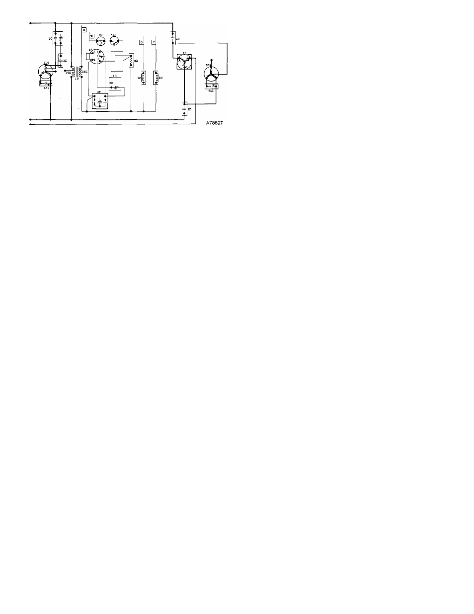
LEGEND
1 B-Transformer
2
C-C
00
I Relay (SPOT)
2D-Contactor (N. O.)
2G-Heat Relay (821) (N. O.)
3D1-Condenser Motor
3D2-Evap Blower Motor
3F-Compressor
4A1 & 4A2-Run Capacitors
5F-Gas Valve
6F-Pilot Igniter
6H-Safety Pilot (Flame Sensing)
7H-Limit Switch (SPST)
*7P-Pressure Switch (N. O.)
“Pressure switch 7P required on propane units only.
Figure 13—Typical Line-to-Line Wiring Diagram
b. Leak-test unit.
c. Evacuate system.
CAUTION:
Charge unit with exact amount of refrigerant as
shown on unit rating plate.
d. Charge unit with proper type and amount of re
frigerant listed on unit rating plate. It is recom
mended that a volumetric charging cylinder or an
accurate scale be used.
4. Check to be sure all tools and loose parts have been re
moved.
5. Check to be sure all panels and covers are in place. Fol
lowing this initial inspection, unit may be started.
B. Evaporator Airflow & Airflow Adjustments
Model 585B units are equipped with a direct-drive blower
motor. Motor speeds have been factory-set for both heating
and cooling to deliver the proper airflow under normal static
pressures.
For cooling operation, the recommended evaporator airflow
is 350 to 450 ft^/min per 12,000 Btuh of cooling. For heating
operation, it is recommended that the airflow produce a tem
perature rise that falls within the range stamped on the unit
rating plate.
1. Determining Evaporator Airflow
Table VI shows air delivery at various temperature rises and
Table VII shows air delivery at various static pressures. Re
fer to these tables to determine the airflow.
NOTE:
Optional field-installed high-static blower packages
are available for sizes 036075 through 060150, single-phase
units. For air delivery applicable to these units, refer to the
air delivery data in Table VII for the equivalent size 3-phase
unit. (Three-phase units have factory-installed high-static
blowers.)
2. Airflow Adjustments
WARNING:
Disconnect all electrical power to the unit
before adjusting airflows.
Motor speed settings can be changed by changing motor lead
connections. The motor leads are color-coded as follows:
black = high speed
blue = medium speed
red = low speed
Sizes 018050, 024050, 036075, 036125, 042100, and 048125
single-phase units; and the 208/230-V, 3-phase version of
size 036075 have a 2-speed motor and do not have the blue
lead for medium speed.
All 460-V units operate on the same speed for both heating
and cooling. Size 036075 460-V units have a 2-speed motor.
Size 048125 and 060125 460-V units have a 3-speed motor.
For all 208- and 230-V units, the motor lead connected to the
heating relay 2G determines the heating speed, and the mo
tor lead connected to the cooling relay 2C determines the
cooling speed. See the unit wiring label. To change the heat
ing and/or cooling speed, connect the appropriate color-
coded motor lead to the appropriate relay. Be sure to tape
unused motor lead(s).
When the same speed is desired for both heating and cooling
for 208- and 230-V units, connect the appropriate color-
coded motor lead to either relay and connect a field-supplied
jumper between the two relays.
For all 460-V units, the single motor lead connection to the
blower relay 2A determines the single motor speed for both
heating and cooling. See unit wiring label. To change the
single motor speed, connect the appropriate color-coded mo
tor lead to the blower relay 2A. Be sure to tape unused motor
lead(s).
C. Checking Unit Operation
Perform the following steps to make certain the unit is
operating properly:
1. Place thermostat SYSTEM switch in COOL position;
place FAN switch in AUTO position; set thermostat set
ting below room temperature. Observe that compressor,
condenser fan motor, and blower motor are all running.
Observe that all motors stop when thermostat is
satisfied.
CAUTION:
Do mu tapid i'vi ’lo ci.inii)re.-; boTweeti cyclc>. Kapid-cycling can cause conijirossor damage. 2. Move thermostat fan switch to ON position. Observe that blower fan runs continuously with thermostat set above or below conditioned space temperature. D. Sequence of Operation (Cooling) The following sequence of operation pertains to Model 585B, 208- or 230-V, 3-phase units; sizes 036075, 036125, 042100, or 048125; however, the sequence of operation of all units is very similar. Refer to the line-to-line wiring diagram in Figure 13. NOTE: Although the actual unit wiring may vary slightly from that shown in Figure 13, the sequence of operation will not be affected. With the room thermostat SYSTEM switch in COOL and FAN switch in AUTO, the sequence of operation is as fol lows: When there is demand for cooling by the room thermostat, terminal R “makes” to terminals Y and G through the ther mostat. This circuit connects the compressor contactor coil 2D and cooling blower relay coil 2C across the 24-volt sec ondary of the transformer IB to energize the compressor contactor and blower relay. The contacts of the energized blower relay 2C close, completing the circuit through the single-phase blower motor 3D2, starting the motor in stantly. The contacts of the energized compressor contactor ■12-