Bryant 585B User Manual
Page 4
Attention! The text in this document has been recognized automatically. To view the original document, you can use the "Original mode".
X =a|-INCHES(ALL OTHER UNITS)
Figure 3 —Condenser Fan Setting
III. GAS PIPING
A separate gas supply line should be installed to run directly
from meter to heating section. Check the local utility for
recommendations concerning existing lines. Choose a supply
pipe large enough to keep pressure loss as low as practical.
Never use pipe smaller than gas connection to heating sec
tion. Observe local codes for all gas pipe installations. Refer
to the national codes indicated on the first page of the in
structions in the absence of local building codes. The fol
lowing are pertinent recommendations:
1. Avoid low spots in long runs of pipe. It is best to grade
all pipe 1/4 inch in every 15 feet to prevent traps. All
horizontal runs should grade downward to risers. Risers
should be used to connect to heating section and to
meter.
2. Install drip leg in riser leading to heating section. Drip
leg will function as trap for dirt and condensate. Install
drip legs where condensate will not freeze.
3. Install external manual shut-off valve in gas supply
pipe near heating section.
CAUTION: I
'n>lal)lo ipperaiioii may (Hcur. parriiailarly
under high wind conditionn. wlmn rhi' gas valve and
manifold a.sscinhly arc fpjrr-ed mU of jinsition while connoci-
ing improperly muled rigid gas piping lo the ga.s valve.
\ haekup wrench should he used whmi making piping eon-
nections
10
avoid sirain on. or distortion ol'. ilit- gas control
piping.
4. Where local codes permit, we recommend using flexible
gas pipe to make connection between rigid, gas piping
and unit gas valve to ensure proper alignment between
manifold orifices and burners. Gas supply pipe enters
unit through access hole provided. See Figure 2 for loca
tion. Gas connection to unit is made to 1/2-inch FPT gas
inlet on gas valve. See Figure 7.
5. Install ground joint union close to heating section be
tween gas valve and manual shut-off valve.
6. Support all piping with appropriate hangers, etc. Use
minimum of one hanger in every 6 feet. For pipe size
other than 1/2 inch, follow recommendations of the na
tional codes.
7. Use joint compound (pipe dope) that is resistant to
action of liquefied petroleum gases.
NOTE: Teflon tape is not recommended.
WARNING: Never use a match or other open flame when
checking for gas leaks.
8. After all connections are made, use soap-and-water solu
tion to check for leaks (or method specified by local
utility regulations) at all field installed and factory in
stalled gas lines.
IV. DUCT CONNECTIONS
Flanges are provided on the unit supply- and return-air
openings for duct connections. See Figure 2 for connection
sizes and locations. See Figures 8, 9, and 10 for illustrations
of typical installations.
NOTE: When installing the accessory plenum or horizontal
economizer, use the accessory Installation Instructions in con-
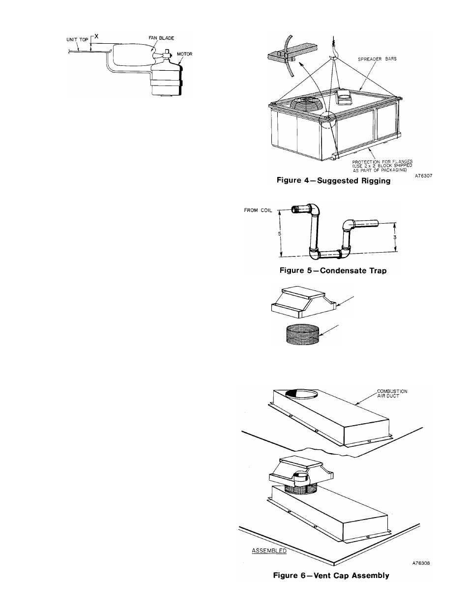
TO DRAIN
VENT CAP
SCREEN
VENT STACK
''EXTENSION
-GASKET