D. base rails, E. condensate drain, Ii. venting – Bryant 585B User Manual
Page 3: 2% of
Attention! The text in this document has been recognized automatically. To view the original document, you can use the "Original mode".
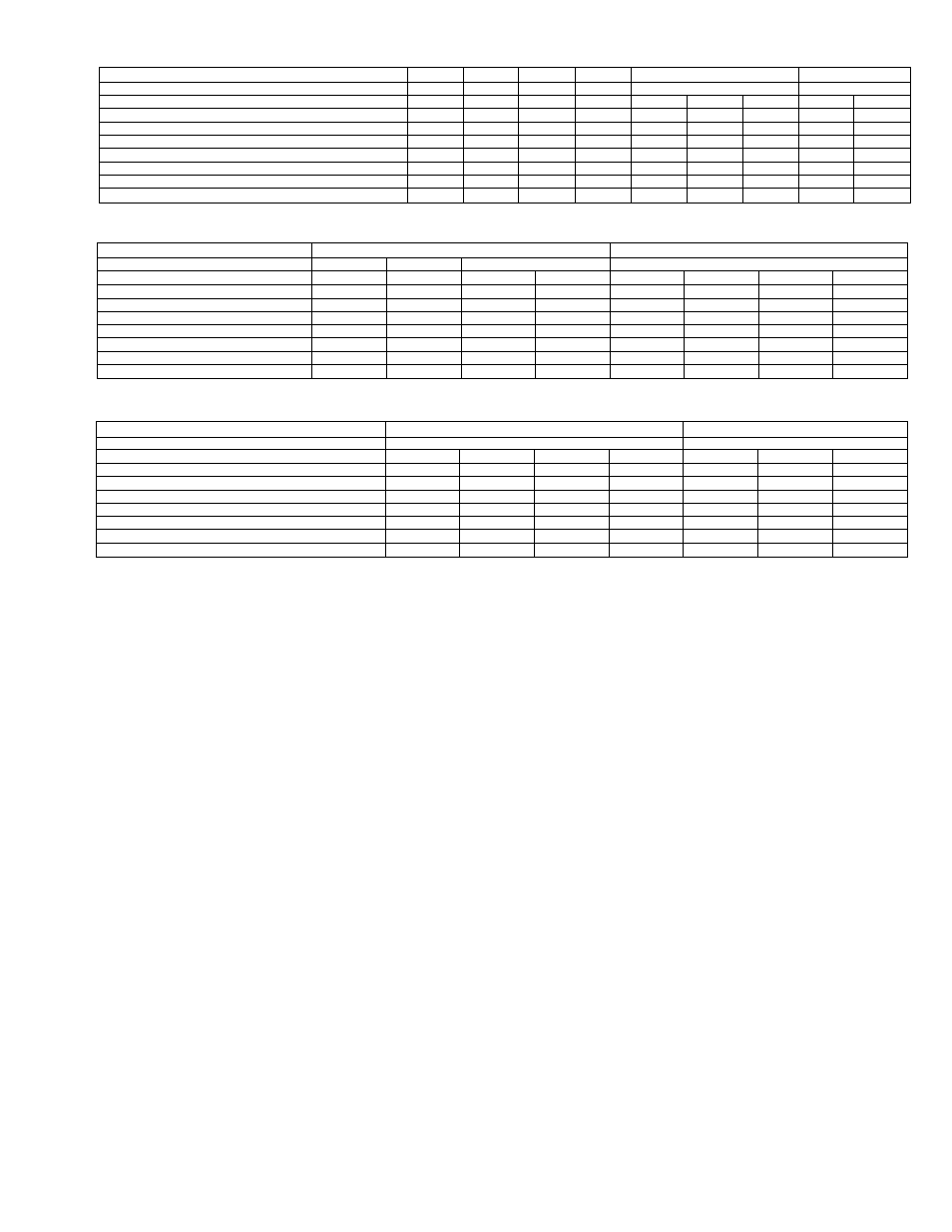
TABLE II-585B ELECTRICAL DATA (Sizes 018050 Thru 036125)
SIZE
018Q50
024050
024075
030075
036075
036125
SERIES
A
A
A
At or Bt
A
A
Unit Volts —Phase (60 Hz)
208/230-1
208-230-1
208-230-1
208-230-1
230-1
208-230-3
460-3
230-1
208/230-3
Operating Voltage Range
187-253
197-253
197-253
197-253
207-253
197-253
414-506
207-253
187-253
Total Unit Amps
14.2
17.2
17.6
22.6
25.6
21.6
10.4
23.8
21.36
Total Power Consumption (Watts)
2600
3200
3200
4150
5300
5300
5300
4750
4750
Max Branch Circuit Fuse Size (Amps)
25
30
30
40
50
30
20
45
30
Unit Ampacity for Wire Sizing
16.7
20.0
21.0
27.0
30.6
24.3
12.2
28.0
22.2
Min Wire Size (AWG) (60"C/75'O*
12/12
12/12
10/10
10/10
8/8
10/10
14/14
10/10
10/10
Max Wire Length (Ft) (60“C/75°O*
90/90
75/75
115/115
90/90
140/140
115/115
220/220
95/95
130/130
TABLE III-585B ELECTRICAL DATA (Sizes 042100 & 048125)
SIZE
042100
048125
SERIES
AT
BT
A
A
Unit Voits—Phase (60 Hz)
230-1
230-1
208-3
230-3
230-1
208-3
230-3
460-3
Operating VoPage Range
207-253
207-253
187-229
207-253
207-253
187-229
207-253
414-506
Total Unit Amps
27.92
30.92
24.6
21.7
31.8
26.56
23.7
12.4
Total Power Consumption (Watts)
5800
5800
5800
5800
6700
6700
6700
6700
Max Branch Circuit Fuse Size (Amps)
50
60
40
35
60
45
40
20
Unit Ampacity for Wire Sizing
33.0
37.0
28.3
25.0
38.7
30.8
27.5
14.4
Min Wire Size (AWG) (60”C/75”O*
8/8
8/8
10/10
10/10
8/8
8/8
10/10
14/14
■ Max Wire Length (Ft) (60"C/75’C)*
125/125
115/115
105/105
125/125
105/105
150/150
115/115
185/185
TABLE IV-585B ELECTRICAL DATA (Sizes 060125 & 060150)
SIZE
060125
060150
SERIES
A
A
Unit Volts—Phase (60 Hz)
230-1
208-3
230-3
460-3
230-1
208-3
230-3
Operating Voltage Range
207-253
187-229
207-253
414-506
207-253
187-229
207-253
Total Unit Amps
41.5
29.8
27.0
14.2
41.5
29.8
27.0
Total Power Consumption (Watts) -
8100
8100
8100
8100
8100
8100
8100
Max Branch Circuit Fuse Size (Amps)
80
50
50
25
80
50
50
Unit Ampacity for Wire Sizing
50.0
35.0
32.0
17.0
50.0
35.0
32.0
Min Wire Size (AWS) (60X/75X)*
6/6
8/8
8/8
12/12
6/6
8/8
8/8
Max Wire Length (Ft) (60°C/75’C)*
130/130
130/130
160/160
250/250
130/130
130/130
160/160
* Use copper wire only. Wire size is based on 60°C or 75°C copper conductor at 86°F (30°C) ambient temperature and ampacity shown in table. If other than 60°C or
75°C copper conductor is used, if ambient temperature is above 86°F, or if voltage drop of wire exceeds
2% of
unit rated voltage, determine wire size from
ampacity shown and the Mational Electrical Code. Wire lengths shown are measured one way along the wire path between unit and service panel for minimum
voltage drop.
tSeries designation may be A or B as determined by the compressor used at time of manufacture.
24 inches. Select a location where rain, ice, and snow will not
fall from an overhang and damage the unit top or fan blade,
or flood the unit.
There is no minimum clearance requirement for the bottom
of the unit; therefore, combustible materials can be used for
supports.
D. Base Rails
The base rails are easily removed for a lower profile installa
tion or a better fit to angle iron frames used in some rooftop
installations. To remove the base rails, simply remove the
screws on either end of the rails.
NOTE:
The base rails must not be removed when installing
the accessory unitized curb and plenum.
E. Condensate Drain
The unit is designed to dispose of condensate water through
a 3/4-inch FPT connection on the drain pan. See Figure 2 for
location. It is recommended that a trap be installed in the
condensate drain line to avoid improper drainage. See
Figure 5. The trap should be as close to the coil as possible.
Make sure that the top of the trap is at least 2 inches lower
than the drain pan connection to prevent the drainpan from
overflowing.
Prime the trap with water and check the condensate line for
leaks.
If the installation requires draining the condensate away
from the roof or the building, connect a minimum of 7/8-inch
OD copper tubing, 3/4-inch galvanized pipe, or 7/8-inch
plastic pipe, and pitch downward at a slope of at least 1 inch
in every 10 feet of horizontal run.
CAUTION:
Do not imdtTsizf conden.sate drain connection.
Consult local codes for additional restrictions and/or precau
tions.
II. VENTING
NOTE:
The vent cap assembly is shipped in the blower com
partment with sizes 018050 and 024050. Remove the blower
access door to locate the assembly. This assembly is shipped
in the control compartment with all other sizes. Remove the
control access door to locate the assembly. See Figure 2 for
the location of these access doors.
CAUTION:
The veniin g system has been designed to ensure
proper venting, fhe vent cap assembly niii.st be installed
only as indicated in this section of the unit Installation In
structions.
NOTE:
Screw holes in the vent stack extension and the vent
cap are not symmetrically located to ensure proper orienta
tion when installing these components.
Refer to Figure 6 and install the vent cap assembly as fol
lows:
1. Place gasket and vent stack extension through hole in
combustion air duct and orient screw holes in base of
vent stack extension with holes in unit top.
2. Secure gasket and vent stack extention to unit top with
screws provided.
3. Place vent cap onto vent stack extension and orient
screw holes in vent cap with holes in extension.
4. Secure vent cap in place with screws provided.
5. Form flat wire screen provided into circular shape
around protruding lip of combustion air duct.
6. Bend wire ends through holes of screen mesh to secure
screen in place.
-3-