4 conduit, 5 power supply coro, 6 ground fault circuit interrupters – Generac Power Systems 004270-1 User Manual
Page 34: 7 isolating different power sources, Conduit, Power supply cord, Groxmd fault circuit interrupters, Isolating different power sources
Attention! The text in this document has been recognized automatically. To view the original document, you can use the "Original mode".
INSTALLATION
Section
2
- Installation
QUIETPACT™ 75D Recreational Vehicle Generator
♦ 2.6.4 CONDUIT
Route the connections between the generator and the
junction box through approved, flexible conduit. The
following general rules apply:
•
All wiring, conduit, and interconnections must be
installed
in
compliance
with
applicable
codes,
standards, and regulations.
• Cut wiring to the required length, and allow extra
wire for junction box connections.
•
Carefully prepare conduit ends to prevent sharp
edges from cutting through wiring insulation.
• Route conduit so it does not interfere with genera
tor movement.
• If you use metallic conduit, vapor-seal the end of
the conduit where it enters the junction box. Do
this because flexible metallic conduit is not vapor-
proof along its entire length.
• All openings in the generator compartment for the
passage of wiring and conduit must be sealed and
made vapor-tight.
NOTE:
Use a high-quality silicone rubber base sealant or
other approved method (such as, explosion-proof
fittings) to seal such openings.
• 2.6.5 POWER SUPPLY CORO __________________ _
The power supply cord must comply with all applic
able codes, standards, and regulations. It must be
large enough to handle the full amperage to which it
will be subjected.
♦ 2.6.6 GROUND FAULT CIRCUIT INTERRUPTERS
The
National
Electrical
Code
(NFPA
70,
551-7)
requires that you install ground-fault circuit inter
rupters (GFCIs) on all external and some internal
electrical receptacles. Contact your manufacturer or
dealer for recommendations.
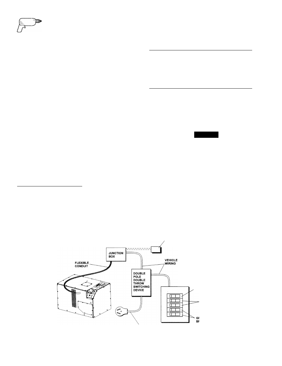
# 2.6.7 ISOLATING DIFFERENT POWER SOURCES
Connections from the junction box must terminate in
a double-pole, double-throw transfer switch (Figure
2.17).
An
alternate
method
for
isolating
different
power sources includes using an isolating receptacle
(Figure 2.18). Whichever method you use, you must
be certain that both power sources are NOT connect
ed at the same time.
DANGER
A
If the vehicle's electrical circuits can be powered by
any other source of electricity (such as, a "dock-
side" power receptacle), there must be no possibil
ity of connecting the different power sources to
the vehicle's circuits at the same time. The dock-
side (utility) power source must be positively iso
lated from the vehicle's circuits whenever the gen
erator is operating. Failure to isolate the vehicle's
circuits from the dockside power supply when the
generator is running may result in damage to the
generator or in serious Injury or death to dockside
(utility) power workers due to backfeed of electri
cal energy. Installation and connection of the gen
erator must comply with NFPA 70, Article 551, and
NFPA 1192 (latest editions).
Figure 2.17 - Transfer Switch Isolation Method
FROM 20 AMP
HACR BREAKER
2ND AIR
CONDITIONER
VEHICLE AC
DISTRIBUTION
PANEL
30 AMP
MAIN BREAKER
HACR
BREAKERS
FOR AIR
CONDITIONERS
POWER SUPPLY CORD
32 Generac* Power Systems, Inc.