Repair & adjustment – Sears 917.254710 User Manual
Page 25
Attention! The text in this document has been recognized automatically. To view the original document, you can use the "Original mode".
REPAIR & ADJUSTMENT
Front'To-FSear Mower Adjustment
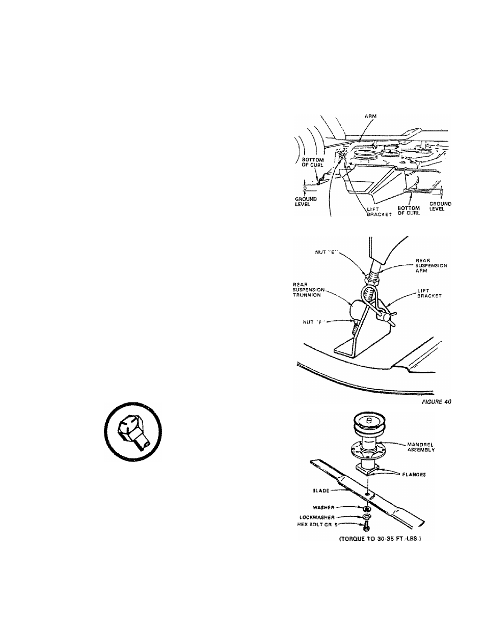
a To obtain the best cutting results, your mower
housing should be adjusted so the front arid rear
flange distanca "D" IFig. 39) is 1/2" lower in
(rant when the mower Is positioned in the highest
cutting positiofi. NOTE; MEASURE DISTANCE
"D" FROM GROUND LEVEL TO BOTTOM OF
CURL ON RIGHT REAR FLANGE AND COMPARE
TO DISTANCE "0" AT RIGHT FRONT FLANGE
b. Ta raise rear of mower, ¡oosartnut "E"on both
rear suspension arms. Screw both nuts "F" up
an EQUAL NUMBER OF TURNS (Fig, 40}.
c.
When distance "D"is 1/2"lower at front than
rear, tighten nuts "£"
d.
To lower rear of mower, loosen nut "F" on
both rear suspension arms an EQUAL NUM
BER OF TURNS (Fig. 40).
a. When distance "D"ls 1/2"tower st from than
rear, retighten nuts "E".
NOTE: WHEN ADJUSTING REAR SUSPENSION TRUN
NIONS, ALWAYS ADJUST BOTH EQUALLY SO MOWER
WILL STAY LEVEL.
9 Biede Replacement
Raise mower to highest position to permit access
to blades or remove mower (page 24).
a. Remove bolt, lockwasher and washer (Fig 41)
(turn counterciockwfSBl(/"^J.
b, Remove and discard old blade.
c Clean top and bottom of mower housing.
d Place new blade between flanges, (the word
"TOP*' is
stamped on ail blades
to
assure proper
instBlIationi, and secure with washer, lockwasher
and bolt previously removed. TIGHTEN SECURE
LY. Torque
to
30-35 ft. lbs.
always
USE GRADE 5 HEAT TREATED
BOLTS TO ATTACH BLADES. CHECK
BOLTS IN BLADES OCCASIONALLY TO
MAKE SURE BOLTS ARE TIGHT. TORQUE
BOLTS TO 30 3S FT- LBS.
A GRADE 5 HEAT TREATED BOLT
CAN BE IDENTIFIED BY THREE
LINES ON THE BOLT HEAD AS
SHOWN AT LEFT.
10, Rear Wheel Inatallatlon
Coat axle with grease to prevent corrosion or rust
accumulation and eventusi seizing of wheel hub
to axle shaft
WHEN REPLACING WHEELS ON THE
TRACTOR, THEY MUST BE MOUNTED
WITH THE LONG HUB SIDE TOWARD THE
CENTER OF THE TRACTOR. INCORRECT
INSTALLATION COULD AFFECT LATERAL
STABILITY, iSEE FIG.44).
RÎAP
SUSPËNSSON
PEAR
SUSPENSION
TmjNNION
FIGUFF 39
FIGURE 41
2^