Sears 113242502 User Manual
Page 9
Attention! The text in this document has been recognized automatically. To view the original document, you can use the "Original mode".
Lay REAR FENCE GU!DE BAR on tab!s to act as a
straightedge. If outer edge of extension is higher or lower
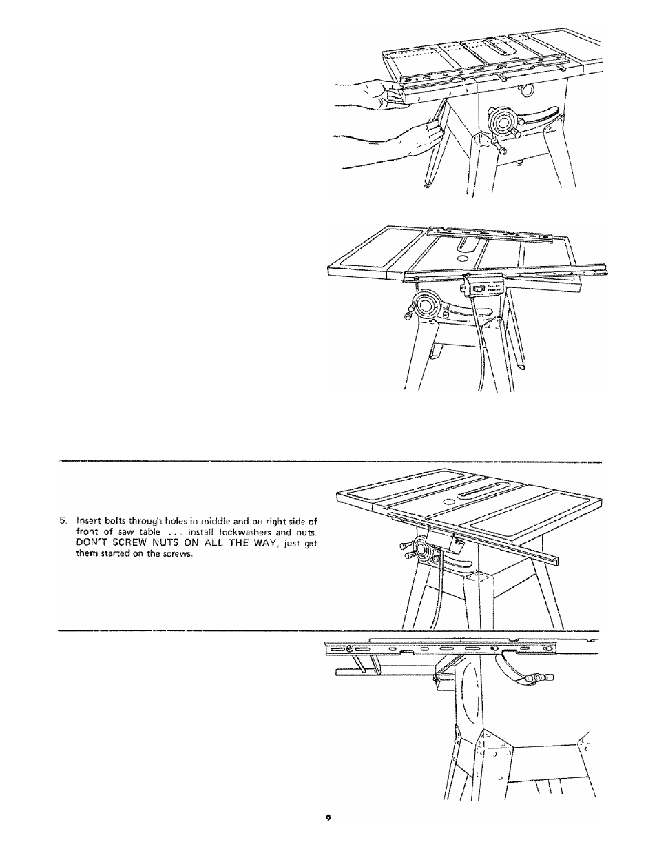
than table surface;
A,
Slightly loosen nuts holding bracket to extension
using 7/16 in, wrench
B,
Move end of extension up or down until outer edge
is even with table surface , .. check with GUIDE
BAR ,, , tighten nuts.
C,
Recheck INNER edge of extension to make sure it
has not moved . readjust, if necessary
INSTALLING RIP FENCE GUIDE BARS
1,
From
among
the
loose
parts
find
the
foNowing
hardware:
2 Hex, Head Screws, 5/16-18 x 1-3/4 in iong
2 Hex Head Screws, 5/1B—18x 1 in long
4 Hex.. Nuts, 5/16-18 fapprox.. dia. of hole 5/16 in, I
4 External Lockwashers, 5/16 in,, iapprox.. dia, of hole
5/16 in )
2 Spacers, 3/4 in. dia. x 1/2 in. long
2 Self-threading nuts
2, Lay guide bars on table.
NOTE: The various holes in the bars allow them to be
repositioned on the saw and also makes them adaptable
to other models.
3,
Insert 1-3/4 in. long screw through the FIRST hole
from the LEFT IN THE FRONT BAR . . , insert
another 1-3/4 in, long screw through LARGE hole at
EXTREME LEFT SIDE OF SWITCH BRACKET thert
through SIXTH hole in bar. Hold them in place with a
piece of masking tape from the underside.
Place spacers on screws.
6 Remove the 3 screws from rear of table extension
7.
Insert 1 in. long screws in FIRST and THIRD holes of
rear bar and attach to table the same way,
8„ Insert ends of FENCE GUIDE BAR ROD through
round holes at outer end of bars,
NOTE: The ends of the ROD are not threaded . , . the
SELF THREADING NUTS will cut threads on the rod
as they are screwed on.