Using featherboards, Adjustments, Not previously noted) – Sears 113242502 User Manual
Page 23: Miter gauge
Attention! The text in this document has been recognized automatically. To view the original document, you can use the "Original mode".
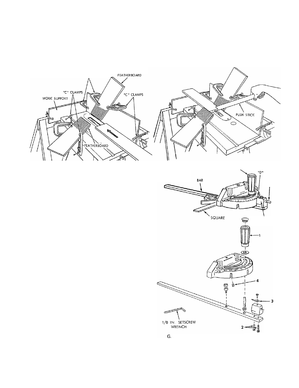
USING FEATHERBOARDS
Add
8
inch high flat facing board to the fence, the full
length of the fence
Use featherboards for ail non "thru-sawing" operations
(when sawbtade guard must be removed), Featherboards sre
used to keep the work in contact with the fence and table
as shown, and to stop kickbacks.
Mount featherboards to fence and table as shown, so that
leading edges of featherboards will support workpiece until
cut is complete, and the workpiece has been pushed
completely past the cutter (sawblade, dado head, molding
head, etc.) with a pushstick, as in ripping
“C" CLAMPS
Before starting the operation (switch "OFF" and cutter
below tabJe surface):
(a) Install featherboards so they exert pressure on the
workpiece; be positive they are secure, and
(b) Make sure by trial that the featherboards will stop a
kickback if one should occur,
Featherboards are not amployad during non thru-sawing
operations when using the miter gage,
Replace the sawblade guard as soon as the non thru-sawing
operation is complete.
ADJUSTMENTS
(Not previously noted)
LOCK kNoa
WARNING: FOR YOUR OWN SAFETY, TURN SWITCH
"OFF" AND REMOVE PLUG FROM POWER SOURCE
OUTLET BEFORE MAKING ANY ADJUSTMENTS.
MITER GAUGE
NOTE: The holes for the stop pin and the graduations are
manufactured to very close tolerances which provide
accuracy for average woodworking in some cases where
extreme accuracy is required, when making angle cuts, for
example, make a trial cut and then recheck it
if necessary, the miter gauge head can be swiveled slightly
to compensate for any inaccuracy,
1. Loosen the "knob" and pull "stop pin" OUT,
2. Swivel the head . , position it at "0" . . push the
stop pin IN ...... lock the handle,
3. The HEAD should be square with the Bar and the
pointer should point to "0". Readjust the poirtter if
necessary.
4. If the head is not square with the bar, adjustments are
required,
A Loosen the "knob" (1) and the "two screws" (2)
8
. Position the HEAD square with the BAR using a
combination square.
C. PUSH the STOP PIN into the slot in the head at
"
0
".......push the pin into the slot and twist it. Lock
the knob,,
0. Recheck with the square,. If the head is still not
square, loosen the screws (
2
) and readjust the
INDICATOR BLOCK,
E, With the head square with the bar and the pin
pushed into the slot, adjust the pointer (3) to point
to "
0
"
F. The miter gauge head must rest on top of the bar
without being able to move up and down , , yet it
must swivel freely.
STOP
PIN
iNOiCATOR
BLOCK
The swiveling movement of the head can be
adjusted by tightening or loosening the setscrew {4}
.... using the
1 / 8
in., setscrew wrench,
NOTE: The setscrew is located inside of the head
To reach it, swivel the head to 60 degrees and tur
the miter gauge upside down.
23