Assembly – Sears 113242502 User Manual
Page 7
Attention! The text in this document has been recognized automatically. To view the original document, you can use the "Original mode".
ASSEMBLY
ATTACHING LEGS
1,
2,
5.
6.
Turn the saw upside down
NOTE: DO NOT LAY IT ON THE FLOOR AS THIS
MAY SCRATCH THE TABLE SURFACE. PLACE IT
ON STRIPS OF WOOD OR PARTS OF THE PACKING
MATERIAL.
From
among
the
loose
parts,
find
the
following
hardware:
16 Hex. Head Screws, 5/16—18 x 5/8 in. long
16 Hex. Nuts, 5/15—18 {approx, dia. of hole, 5/16 inj
16 Hex.. Head Screws, 1/4 in.—20 x 1/2 in. long
16 Hex, Nuts, 1 /4—20 (approx, dia. of hole, 1/4 in }
8 Hex.. Nuts, 1/2—13 (approx, dia of hole, 1/2 in.)
4 Leveling Feet
16 Lockwashirs, 1/4 in. External Type (approx, dia, of
hole, 1/4 in.)
16 Lockwashers, 5/16 in. External Type (approx, dia.
of hole, 5/16 in.)
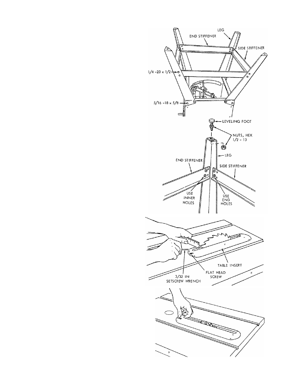
NOTE: The four stiffeners are identical. BE SURE TO
ATTACH
THE
SIDE
STIFFENERS
USING
THE
OUTER
HOLES
...
ATTACH
END
STIFFENERS
USING INNER HOLES,
insert
screws
through
legs
then
through
stiffeners
Install lockwashers and nuts. DO NOT TIGHTEN.
After all screws, washers and nuts are installed, tighten
all nuts.
Install leveling feet.
Place saw in upright position.
BEFORE
PROCEEDING
WITH
THE
ASSEMBLY,
THE
TABLE
INSERT,
BLADE
SQUARENESS,
AND
BLADE
PARALLELISM MUST BE CHECKED AT THIS TIME.
CHECKING TABLE INSERT
1. Insert should be flush with table top. Check as shown.
Loosen flat head screw that holds insert end adjust the
four set screws as necessary. Tighten flat head screw,
Do not tighten screw to the point where it deflects the
insert--
2. To remove insert
A) Loosen Screw
B) Lift insert from front end, and pull toward front of
saw.
3. To replace insert.
Placé insert into insert opening in table and push
toward rear of saw to engage spring clip and until
keyslot in insert will drop over screw. Tighten screw.
Do not tighten screw to the point where it will deflect
the insert.