Sears 113242502 User Manual
Page 12
Attention! The text in this document has been recognized automatically. To view the original document, you can use the "Original mode".
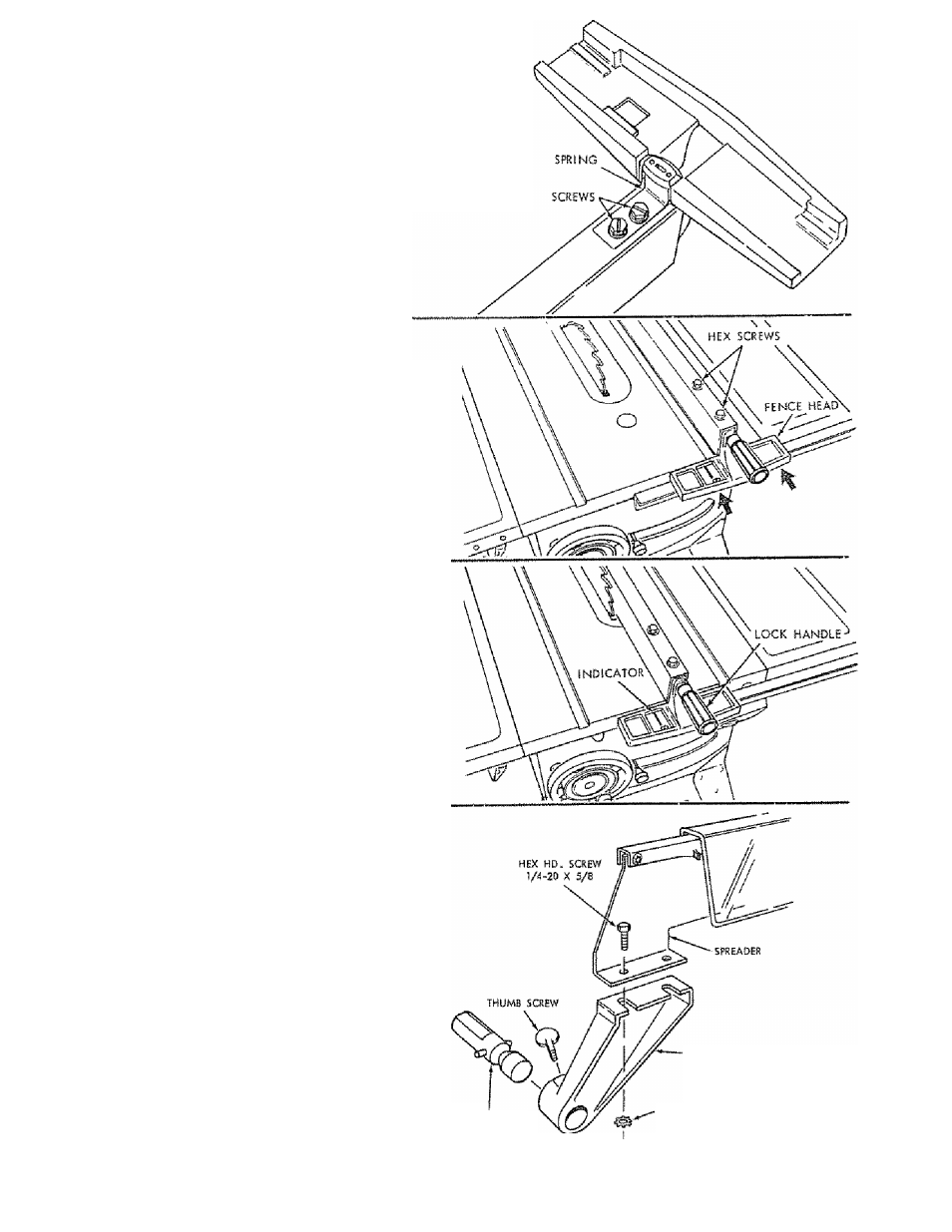
If the fence does not slide easily along the bars, the pressure
of the spring can be REDUCED.
1. Loosen the screws,.
2.
Move spring slightly toward rear of fence ., tighten
screws.
The rip fence most be PARALLEL with the sawblade
{see page 23) and Miter Gauge grooves . . . Move fence
until It is along side of groove. Do NOT LOCK IT. it
should be parallel to groove. If it is not;
A. Loosen the two "Hex.. Head Screws "
B. Hold fence head tightly against bar ... move end
of fertce so that it is parallel with groove,
C. Alternately tighten the screws.
ADJUSTING RIP SCALE INDICATOR
1
Turn ELEVATION handwheel clockwise until blade is
up Bs high as it will go-
IMPORTANT:
BLADE
must
be
SQUARE
(90°)
to
TABLE, in order to ALIGN rip fence.
Position fence on right side of sawblade so that it
touches the sides of the teeth .. tighters lock knob.
Loosen screw holding the indicator - .. adjust indicator
so that it points to "0" .. . tighten screw.
NOTE: if you cannot adjust indicator so that it points
to "0", loosen the screws holding the front guide bar
and move the guide bar,
INSTALLING BLADE GUARD
1. From amoung the loose parts, find the hardware.
2
Attach SPREADER to SPREADER SUPPORT so that
screws are all the way back in the SLOTS of SUPPORT
. .. hand tighten screws.
SPREADEft ROD
SPREADER SUPPORT
LOCXWASHER, EXT
]/i
—-NUT, HEX 1/4
12