Sears 113242502 User Manual
Page 5
Attention! The text in this document has been recognized automatically. To view the original document, you can use the "Original mode".
5,
Aithough the motor is designed for operation on the
voltage and frequency specified on motor nameplate,
normal loads will be handled safely on voltages not
more than T0% above or below the nameplate voStage.
Heavy loads, however, require that voltage at motor
terminals be not less than the voltage specified on
nameplate
6. Most motor troubles may be traced to loose or
incorrect connections. overloBciing, reduced input
voltage iwhtch results when small size wires are used in
the supply circuit) or when the supply circuit is
extremely long. Always check connections, toad and
supply circuit when the motor fails to perform
satisfactorily. Check wire sizes and lengths with the
table in the next paragraph. Replace or repair damaged
or worn cord immediately.
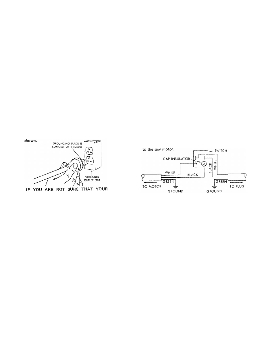
COISIWECTIIMG TO POWER SOURCE OUTLET
This saw must be grounded while in use to protect the
operator from electrical shock.
If power cord is worn or cut, or damaged in arty way, have
ft replaced immediately,
CAUTION: This saw is wired for operation on 240 volts
only, Connect to a 15 ampere branch circuit protected by a
15 ampere time delay or circuit saver fuse or circuit
breaker.
WARNING: Do not permit fingers to contact the terminals
of power or motor plugs when installing or removing the
plug to or from a live power source- Hold the plug as
PROPERLY
GROUNDED,
HAVE
IT
CHECKED
BY
A
QUALIFIED ELECTRICIAN,
WARNING:
IF
NOT
PROPERLY
GROUNDED
THIS
POWER TOOL GAN INCUR THE POTENTIAL HAZARD
OF
ELECTRICAL
SHOCK,
PARTICULARLY
WHEN
USED
IN
DAMP
LOCATIONS,
IN
PROXIMITY
TO
PLUMBING, OR OUT OF DOORS, IF AN ELECTRICAL
SHOCK OCCURS THERE IS THE POTENTIAL OF A
SECONDARY
HAZARD
SUCH
AS
YOUR
HANDS
CONTACTING THE SAWBLADE.
This power too! is equipped with a 3-conducior cord and
grounding type plug which has a grounding prong, approved
by Underwriters' Laboratories and the Canadian Standards
Association. The ground conductor has a green lug and is
attached to the tool housing at orte end end to the ground
prong in the attachment plug at the other end-
The use of any extension cord will cause some loss of
power. To keer- this to a minimum and to prevent
over-heating ar j motor burn-out, use the table below to
determine the minimum wire size (A.W G ) extension cord
Use only 3 wire extension cords which have 3 prong
grounding type lugs and 3-pole receptacles which accept the
tools plug.
Extension Cord Length
Wire Size A,W G.
Up to 100 ft.............................................................. 14
100 ft, to 200 ft................................ ....................... 12
200 ft. to 400 ft ..........................................................8
NOTE: For circuits of greater length, the wire size must be
increased proportionately in order to deliver ample voltage
NO
AOAPrtt rs
AValiABSE FOit
W!S TYPf PLUG
WARRANTY .................. ....................-..........................2
GENERAL SAFETY INSTRUCTIONS
FOR POWER TOOLS ............................. ............ ........ 2
ADDITIONAL SAFETY INSTRUCTIONS
FOR TABLE SAWS........................................................ 3
MOTOR SPECIFICATIONS AND ELECTRICAL
REQUIREMENTS........................................................... 4
UNPACKING AND CHECKING CONTENTS ....... .......... 6
Tools Needed ........ .......................................................6
List of Loose Parts , .............. ................. .......... .......... 6
ASSEMBLY ........... .. ..... ........ .................................. ..... 7
Attaching Legs ......................... .. - — -, ................ 7
Checking Table Insert . .. .......... ......... ....................... .. 7
Checking Blade Squareness to Table .................... , , , , 8
Attaching and Assembling Table Extensions ................. 8
instelling Rip Fence Guide Bars ................................... 9
Aligning Rip Fence ......... .................... , .................... 11
Adjusting Rip Scale Pointer ,
.. .............. ..,
12
Installing Blade Guard .............. ............ .... .............. 12
GETTING TO KNOW YOUR SAW ....... ..:................ 14
On-Off Switch ............................................................. 14
Elevation Handwheel ................................................ 15
Elevation Lock .................................... ..................... . 15
Tilt Crank .... .................... .... ................................. .. 15
Rip Fence ............................................................... 15
Miter Gauge...................... . ,............. ........... ............ 15
Blade Guard
..... .................... -.......... ......... . 15
Table Insert ................................................................. 15
Removing and Installiftg Sawfalade ................ ........... 16
OUTLET IS
CONTENTS
Exactf-Cut
BASIC SAW OPERATION USING THE MITER GAUGE
Work Helpers.............
....
Crosscutting . .......................
Repetitive Cutting.................
Miter Cutting
Bevel Crosscutting ...............
Compound Miter Cutting ..................................... ... ..
BASIC SAW OPERATION USING THE RIP FENCE
Ripping
Bevel Ripping
16
17
17
18
18
19
19
19
20
20
20
21
22
22
22
23
23
23
Ploughing and Molding
Resawing ,
............
Cutting Panels.............
Rabbeting — ..
Using Featherboards .
ADJUSTMENTS _____
Miter Gauge ,, .. ..........
Heeling Adjustment or Parallelism of
Sawblade to Miter Gauge Groove ., , ------------. ,, .
24
Blade Tilt, or Squareness of
Blade to Table ......................................................... 25
Elevation Lock .............................................. .......... ... 26
MAINTENANCE ........................................................ 26
LUBRICATION ....................................................... 27
RECOMMENDED ACCESSORIES .............................. 27
TROUBLE SHOOTING ............................................ . 28
REPAIR PARTS ......................................................... 30