Vtillnli – Sears 831.15403 User Manual
Page 17
Attention! The text in this document has been recognized automatically. To view the original document, you can use the "Original mode".
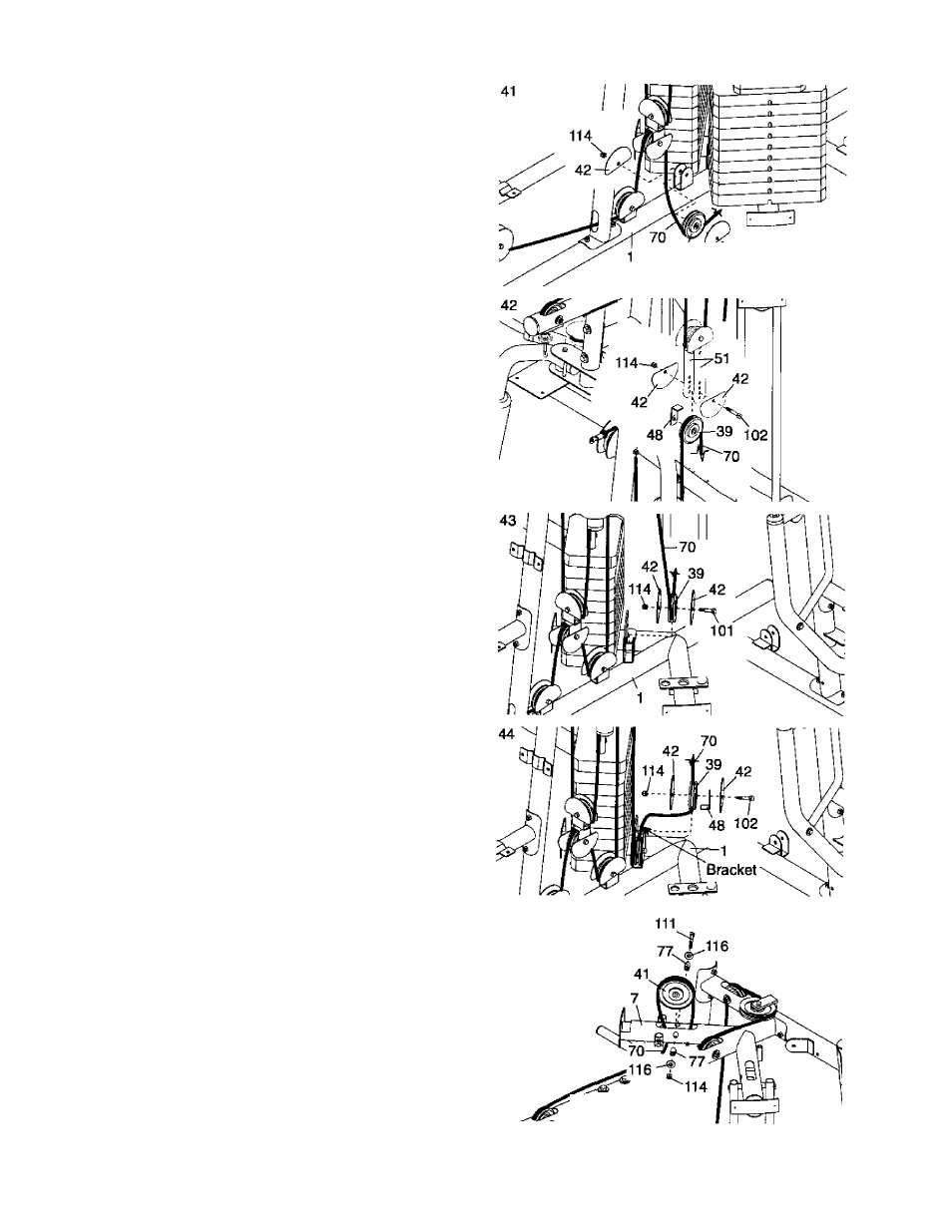
41. Wrap the Leg Lever Cable (70) under a 90mm
Pulley (39). Attach the Pulley and two Half Finger
Guards (42) to the Right Base (1) with an M10 x
48mm Bolt (101) and an M10 Nylon Locknut
(114).
Make sure the Finger Guards are orient
ed as shown.
42. Wrap the Leg Lever Cable (70) over a 90mm
Pulley (39). Attach the Pulley, a Small Cable Trap
(48), and two Half Finger Guards (42) at the sec
ond hole from the bottom of the two Pulley Plates
(51) with an Ml 0 X 52mm Bolt (102) and an M10
Nylon Locknut (114).
Make sure the Cable Trap
and Finger Guards are oriented as shown.
43. Wrap the Leg Lever Cable (70) under a 90mm
Pulley (39). Attach the Pulley and two Half Finger
Guards (42) to the “U"-bracket on the Right Base
(1) with an M10 x48mm Bolt (101) and an M10
Nylon Locknut (114).
Make sure the Finger
Guards are oriented as shown and are on the
outside of the “U”-bracket.
44. Wrap the Leg Lever Cable (70) under a 90mm
Pulley (39). Attach the Pulley, a Small Cable Trap
(48), and two Half Finger Guards (42) to the
bracket on the Right Base (1) with an M10 x
52mm Bolt (102) and an M10 Nylon Locknut
(114). Make sure the Cable Trap and Finger
Guards are oriented as shown and that the
bracket is between the Pulley and the Finger
Guard next to the Locknut.
45. Route the Leg Lever Cable (70) up through the
Right Top Frame (7), over all5mm Pulley (41),
and back down through the Top Frame. Attach
the Pulley inside the Top Frame with an M10 x
80mm Bolt (111), two M10 Washers (116), two
19mm Spacers (77), and an M10 Nylon Locknut
(114).
39 1 *^101
42
45
VTillNlI
17