Sears 9MPD125L20B1 User Manual
Page 6
Attention! The text in this document has been recognized automatically. To view the original document, you can use the "Original mode".
Fiçjurp 3
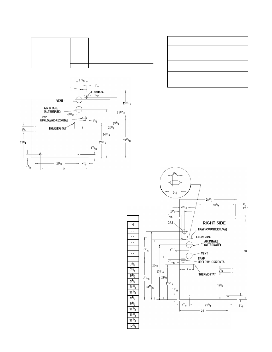
Dimensions & Clearances
^ F
—
TOP
AIR INTAKE
^'^UENT (’9MPD)
_l "
G H------------------------------------------ A-
^ E
^ ^ ^ ^
LEFT SIDE
TRAP (COUNTERFLOW)
GAS^^
FRONT
MINIMUM CLEARANCES TO
COMBUSTIBLE MATERIALS FOR ALL UNITS
REAR
0
FRONT (combustion air openings in
furnace and in structure)
3"
Required For Service
•24”
ALL SIDES Of SUPPLY PLENUM
1"
SIDES
0
VENT
0
TOP OF FURNACE
1"
*30" clearance recommended for casing removal.
Horizontal position: Line contact is permissible only between
lines formed by intersections of top and two sides of furnace
jacket, and building joists, studs or framing.
NOTE: Evaporator "A” coil drain pan dimensions
may vary from furnace duct opening size. Always
consult evaporator specifications for duct size
requirements.
Furnace is designed for bottom return or side
return.
Return air through back of furnace is NOT allowed.
BOTTOM
231/0
Drawing is representative,
but some models may vary
ALL DIMENSIONS IN INCHES
Unit
Capacity
N9MP1050B12A
N9MP1075B12A
N9MP1080F16A
¡\I9MP1100F14A
N9MP1100J20A
N9MP1125J20A
N9MP2050B12A
N9MP2075B12A
N9MP2080F16A
N9MP2100F14A
N9MP2100J20A
N9MP2125J20A
•9MPD050F12A
•9MPD075F12A
‘9MPD080J16A
*9MPD100J14A
'9MPD100J20A
‘9MPD125L20A
Cabinet
'¡5.V2
151
/,
I
9
I/R
191/
r
22
\
22\
m
V,
^SV,
nV,
MVa
22
\
22V,
nV.
m
V
u
22
V.
21
V.
22
V.
241
/,
B
14
14
175
/s
21
V
4
2VU
14
14
2VU
2VU
175
/s
17=/«
2lVr
21V
a
21V
a
23
Bottom
1=/s
2V
b
2V
b
II
5/16
115/16
2i/a
21/
r
115/,
16
115/16
21/
r
2V
r
115/,
16
115/,
16
l15/i(
D
125/e
125/
r
145/4
145/4
185/4
185/4
125/
r
125/
r
145/4
145/4
185/4
185/4
145/4
145/4
185/4
185/4
185/4
23
Top
43
/c
45/
r
45/
r
45/
r
43
/c
45/
r
4
I/,
4
I/?
4
I/,
4
I/,
41
/,
41
/,
4
I/,
4
I/,
4
I/?
41
/,
4
I/,
4
I/,
21/,
2V,
25/
r
25/
r
25/
r
2
I
/4
25-23-36b
440
01 1020 04