Figuro 30, Typical gas piping for upflow, Figure 31 – Sears 9MPD125L20B1 User Manual
Page 32: Typical gas piping for downflow, Gas piping requirements
Attention! The text in this document has been recognized automatically. To view the original document, you can use the "Original mode".
3.
Time how many seconds it takes the smallest dial on the gas
meter to make one complete revolution. Refer to Example.
4.
Relight all appliances and ensure all pilots are operating.
NOTE: If meter uses a 2 cubic foot dial, divide results (seconds) by
two.
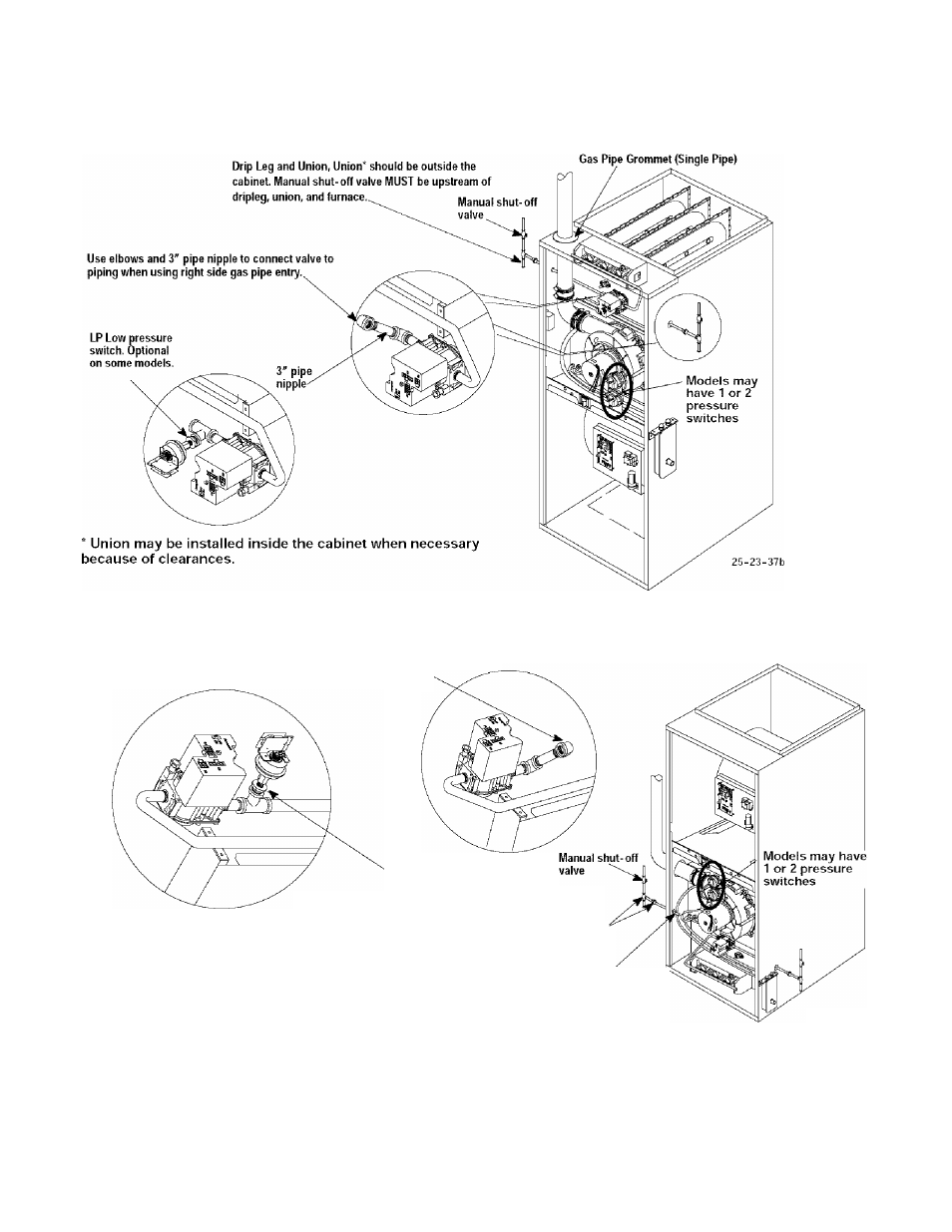
Figuro 30
Typical Gas Piping for Upflow
Figure 31
Typical Gas Piping for Downflow
Use elbows and 3" pipe nipple to connect valve
to piping when using left side gas pipe entry.
LP Low pressure
switch. Optional LP
conversion.
Drip Leg and Union, Union* should be outside-'
the cabinet. Manual shut-off valve MUST be
upstream of dripleg, union, and furnace.
Gas Pipe Grommet*
’Union may be installed inside the cabinet when necessary
(Single Pipe)
because of clearances.
25-23-39
Gas Piping Requirements
NOTE: The gas supply line must be installed by a qualified service
technician in accordance with all building codes, (In the state of
Massachusetts, gas supply connections MUST be performed by a
licensed plumber or gas fitfer).
1.
Properly size gas pipe to handle combined appliance load
or run gas pipe directly from gas meter or LP gas regulator.
Refer to NFGC and ANSI Z223.1 for proper gas pipe size.
2.
Install correct pipe size for run length and furnace rating.
3.
Measure pipe length from gas meter or LP second stage
regulator.
[32]
440
01 1020 04