Sears 9MPD125L20B1 User Manual
Page 21
Attention! The text in this document has been recognized automatically. To view the original document, you can use the "Original mode".
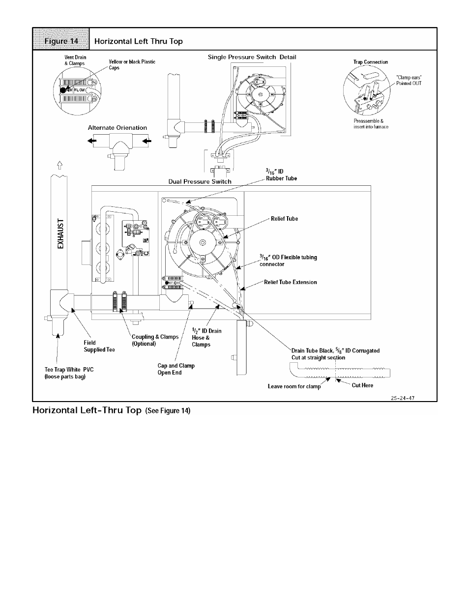
Disconnect the hoses from the Trap assembly, and remove Trap
and Trap mounting bracket from the blower compartment. Using
cover plate and gasket provided in the loose parts bag, cover the
hole from the burner compartment to the blower compartment and
secure with screws.
Mount the Trap externally to the bottom side of the unit using the
2
screws provided in the location shown.
Cut the corrugated tube as shown in the illustration above. Con
nect the corrugated hose from the transition to the Trap. Secure
connections with clamps.
Remove the black V
2
" ID Drain Tube from the Drain Tee. Install
a yellow cap and clamp over the open drain port of the Drain Tee.
Connect the black V
2
" ID Drain Tube from the Vent Drain to the
Trap. Secure connections with clamps.
Connect the ^/-ig" ID relief tube to the middle port on the Trap. If an
extension is required, use the ' OD flexible tubing connector
and the black ^/-|g'' ID relief tube in the loose parts bag. Cut tube
to length. Secure all connections with clamps.
Cut an appropriate length of 2" PVC pipe, long enough to exit the
cabinet and connect the vent drain to either:
•
A standard field supplied
2"
PVC tee (N9MP1 and 2 mod
els), or
•
A 2" PVC coupling fastened onto the Drain Tee (*9MPD
models)
Install Tee Trap into bottom section of Tee.
Connect the Tee trap and the main drain line exiting the casing as
shown in Figure 18.
Note: It is recommended that all PVC piping and fitting connec
tions be fit up and inspected before final cementing. Both the ex
ternal Trap and the external Tee Trap must be primed before
operation. Verify all condensate drain connections are securely
clamped. A coupling and clamps (in loose part bag) may be
installed as shown for future servicing of the vent system.
440
01 1020 04
CHI