Connecting vent pipes and termination, Warning – Sears 9MPD125L20B1 User Manual
Page 26
Attention! The text in this document has been recognized automatically. To view the original document, you can use the "Original mode".
The air intake coupling is sized for 2" PVC pipe.
Install the combustion air pipe to the air intake coupling using RTV
sealant to provide for future serviceability.
Vent Pipe Connection
Install the vent pipe grommet to the furnace panel. Locate the
grommet in the furnace panel at a location directly away from the
vent fitting on the combustion blower. The grommet snaps into the
3 " hole plug from the furnace panel. NOTE: Depending on the
installation position, the vent pipe grommet will be installed to the
top panel or to the alternate location on the side panels. If needed,
remove the 3" hole plug from the furnace panel and relocate to the
open hole in the furnace panel. (See Figure 9 or Figure 18)
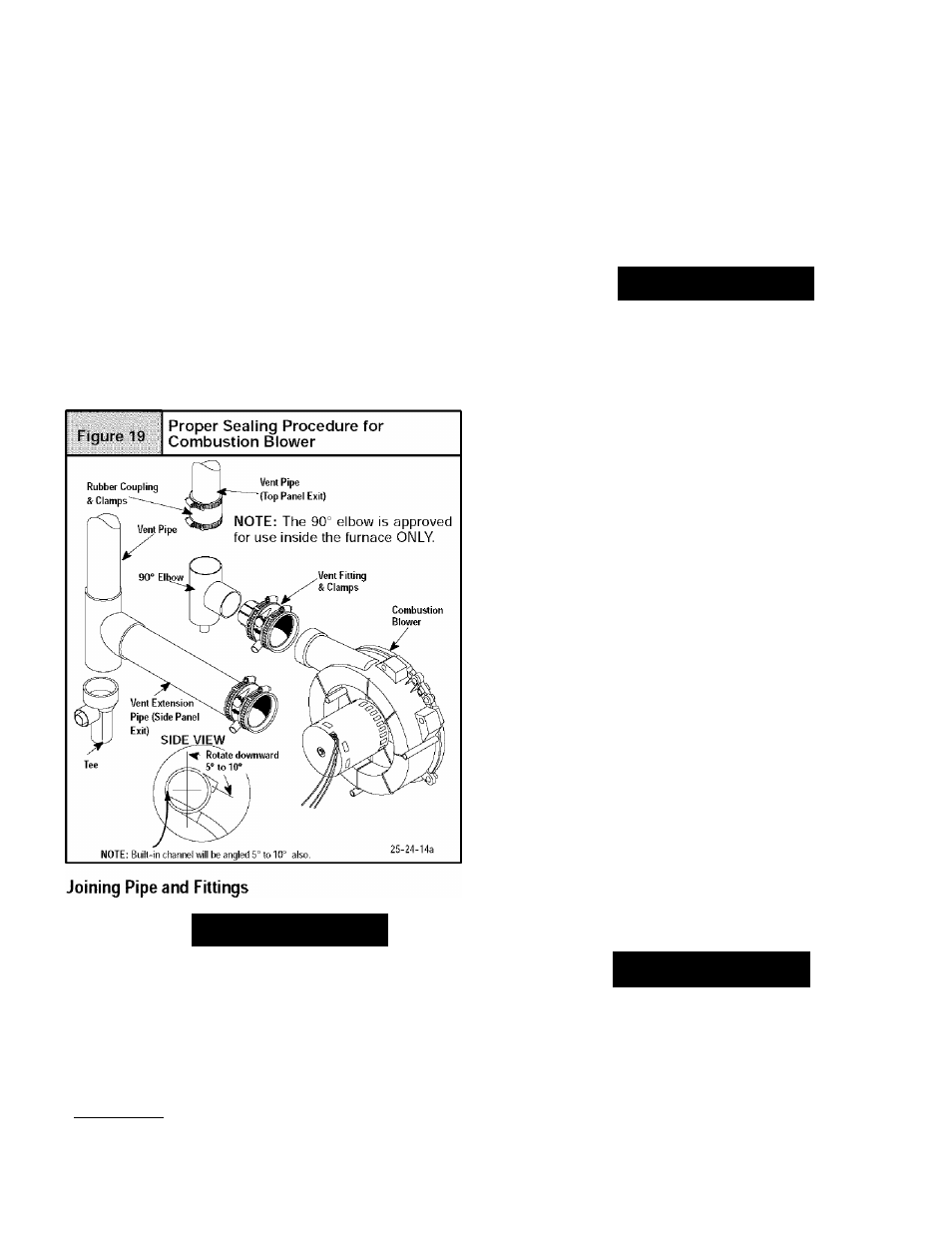
Install the vent pipe to the rubber coupling, the vent fitting or the
PVC vent extension pipe. Securely attach using the clamp or PVC
cement as required.
Note: The vent fitting MUST be installed with the air flow
marking arrow pointed toward the vent pipe. (See Figure 19)
Some installations require the vent fitting to be installed with
a 5“ to 10° downward slope. (See Figure 9 thru Figure 18)
WARNING
FIRE HAZARD
Failure to do so could cause personal injury and/or
property damage.
Observe all cautions and warnings printed on
material containers
Provide adequate ventilation and do NOT assemble
near heat source or open flame. Do NOT smoke
while using solvent cements and avoid contact with
skin or eyes.
This furnace is approved for venting with Schedule 40 PVC,
CPVC, ABS, Cellular Core pipe fittings and SDR-26 PVC.
NOTE: All PVC, CPVC, ABS, and Cellular Core pipe fittings, sol
vent cement, primers and procedures MUST conform to American
National Standard Institute and American Society for Testing and
Materials (ANSI/ASTM) standards.
•
Pipe and Fittings - kSlU
D1785, D2241, D2466, D2661,
D2665, F-S91, F-628
•
PVC Primer and Solvent Cement ~
ASTM D2564
•
Procedure for Cementing Joints -
Ref ASTM D2855
NOTE: In order to create a seal that allows future removal of pipe,
RTV sealant MUST be used on the inlet pipe where itjoins to the
furnace. PVC, CPVC, ABS, and Cellular Core pipe and cement
may be used on all other joints.
WARNING
in
CARBON MONOXIDE POISONING HAZARD
Failure to follow this warning could result
personal property damage, injury or death.
Do NOT use solvent cement that has become
curdled, lumpy or thickened and do NOT thin.
Observe precautions printed on containers. For
applications below 32° F., use only low temperature
type solvent cement. Poor Joints may lead to
disconnected or leaking vent pipe Joints allowing
carbon monoxide to enter the living space.
1.
Cut pipe end square, remove ragged edges and burrs.
Chamfer end of pipe, then clean fitting, socket and pipejoint
of all dirt, grease, or moisture.
NOTE: Stirthe solvent cement frequently while using. Use a natu
ral bristle brush or the dauber supplied with the cement. The prop
er brush size is one inch.
2.
After checking pipe and socket for proper fit, wipe socket
and pipe with cleaner-primer. Apply a liberal coat of primer
to inside surface of socket and outside of pipe. Do NOT al
low primer to dry before applying cement.
3.
Apply a thin coat of cement evenly in the socket. Quickly ap
ply a heavy coat of cement to the pipe end and insert pipe
into fittings with a slight twisting movement until it bottoms
out.
NOTE: Cement MUST be fluid while inserting pipe. If NOT, recoat
pipe.
4.
Hold the pipe in the fitting for 30 seconds to prevent the ta
pered socket from pushing the pipe out of the fitting.
5.
Wipe all excess cement from the Joint with a rag. Allow 15
minutes before handling. Cure time varies according to fit,
temperature and humidity.
Connecting Vent Pipes and Termination
NOTE: Combustion air intake and vent MUST terminate in the
same atmospheric pressure zone. If installation is in a cold climate
(sustained temperatures below 0°F), increase the minimum dis
tance between vent pipe and air intake from
8
" to 18 '.
WARNING
CARBON MONOXIDE POISONING HAZARD.
Failure to properly vent this furnace could result
in death, personal injury and/or property damage.
Maintain a minimum of 36 between combustion
air inlet and clothes dryer vent. Terminate the
combustion air intake as far as possible from any
air conditioner, heat pump, swimming pool,
swimming pool pumping, chlorinator or filtration
unit.
440
01 1020 04