Figuro 41, Condensate line raised by base, Checks and adjustments – Sears 9MPD125L20B1 User Manual
Page 38: Startup, Fire or explosion hazard, Manifold gas pressure adjustment, Adjust pilot burner, Main burner flame check, Warning
Attention! The text in this document has been recognized automatically. To view the original document, you can use the "Original mode".
Figuro 41
Condensate Line Raised by Base
8. Checks and Adjustments
WARNING
FIRE OR EXPLOSION HAZARD.
Failure to turn OFF gas at shut off before
connecting manometer couid result in death,
personal injury and/or property damage.
Turn OFF gas at shut off before connecting
manometer.
Startup
NOTE: Refer to the start-up procedures in the
"User's Information
Manual'
or to the
"Operating Instructions Labe!'
on the furnace.
WARNING
FIRE OR EXPLOSION HAZARD.
Failure to correct hazard could result in death,
personal injury, and/or property damage.
If any sparks, odors or unusual noises occur,
immediately shut OFF power to furnace. Check for
wiring errors or obstruction to blower.
Gas Supply Pressure
Gas supply pressure should be within minimum and maximum val
ues listed on rating plate. Pressures are usually set by gas suppli
ers.
Manifold Gas Pressure Adjustment
NOTE: Make adjustment to manifold pressure with burners oper
ating.
1.
Remove the burner compartment door.
2.
With gas OFF, connect manometer to tapped opening on
gas valve. Use manometer with a 0 to 15" water column
range.
3.
Turn gas ON and remove adjustment screw cover on gas
valve. Turn counterclockwise to decrease pressure and
clockwise to increase.
4.
For altitudes up to 2000', set pressure to value shown in
Table
6
or Table
8
, ± 0.3' (
8
mm) water column. For alti
tudes of 2000' to 8000', see Section 5 for correct pressure
setting.
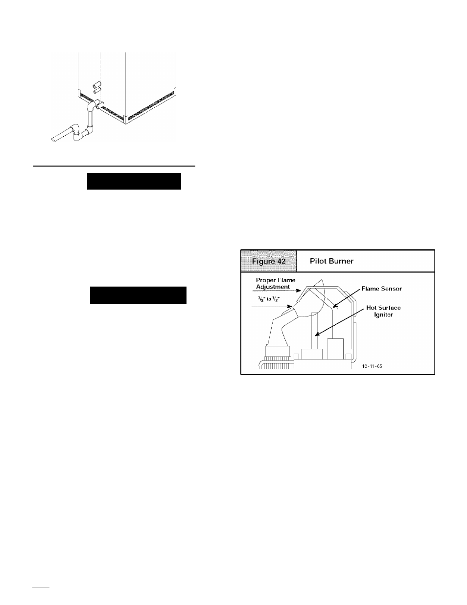
Adjust Pilot Burner
The furnace has a pilot flame to light the main burner. The flame
should surround ^/
3
' to V
2
' of the flame sensor. See Figure 42. To
adjust, remove cap from pilot adjusting screw on gas valve. Turn
screw counterclockwise to increase or clockwise to decrease
flame as required. Replace adjusting screw cap.
Main Burner Flame Check
Allow the furnace to run approximately 10 minutes then inspect the
main burner and pilot flames. See Figure 43.
Check for the following (Figure 43):
• Stable and blue flames. Dust may cause orange tips or
wisps of yellow, but flames MUST NOT have solid, yellow
tips.
•
Flames extending directly from burner into heat ex
changer.
• Flames do NOT touch sides of heat exchanger.
If any problems with main burner flames are noted, it may be nec
essary to adjust gas pressures, or check for drafts.
[38l
440
01 1020 04