Assembly – Sears 113.24907 User Manual
Page 8
Attention! The text in this document has been recognized automatically. To view the original document, you can use the "Original mode".
assembly
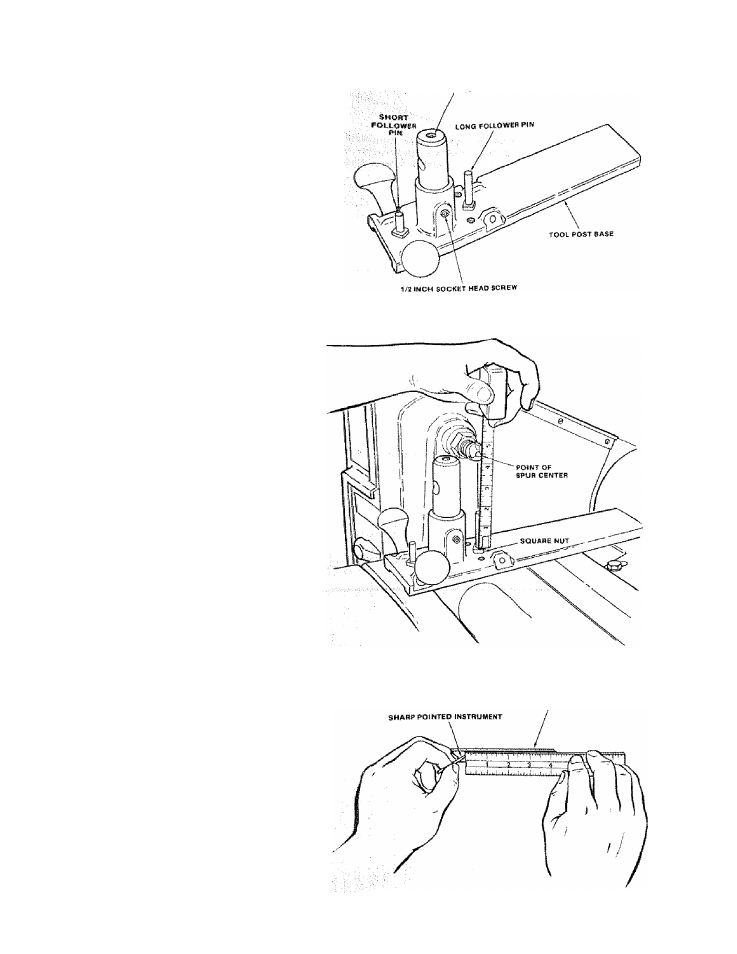
1/Z INCH SOCKET HE AD SCBBW
3.
Screw the Knobs and Follower Pins into the Too! Post
Base, (see illustration).
4. Insert the Tool Post.
^
^
5.
Screw a 1 /2 inch long Socket Head Screw i nto the top
of the Tool Post and into the Tool Post Base a few
turns; do not tighten.
6. An Alignment Gauge is provided to align the tip of the
Cutting Toot with the centerline of the Lathe (see
page 11, number 8). The following steps’explain how
■, ■ this is done. ■ ■ ■■ ■ -: , ■ ■
,
a. Measure the distance from the top of the Square
Nut to the point of the Spur Center as shown.
ALIGNMENT GAUGE
b.
Using a sharp pointed instrument, scratch a mark ;
on both inside surface of the Alignment Gauge as
shown. The distance between the scratch line and
one end of the Alignment Gauge should be equal to
the above;rhsasurement.
.
8