& [if – Carrier 38HQ User Manual
Page 9
Attention! The text in this document has been recognized automatically. To view the original document, you can use the "Original mode".
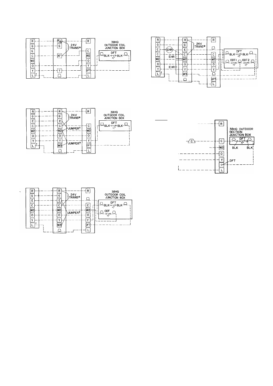
THERMOSTAT 40AQ OR 40QB FAN COIL 38HQ
SUBBASE COOLING CONTROL COMPRESSOR
HH93AZ073 OR
KIT
SECTION
HH93AZ075 TERMINAL BOARD TERMINAL BOARD
COOLING AND ONE-STAGE HEATING
(38HQ/40AQ OR 40QB WITHOUT ELECTRIC HEATER)
A
THERMOSTAT 40AQ, 40QB OR 40FQ
38HQ
SUBBASE ELECTRIC HEATER COMPRESSOR
HH93AZ073 0R TERMINAL
SECTION
HH93AZ075
BOARD
TERMINAL BOARD
COOLING AND TWO-STAGE HEATING
(38HQ WITH 40AQ,40QB OR 40FS/28HQ/VQ
EQUIPPED WITH ELECTRIC HEATER-,
SUPPLEMENTAL HEAT, NO OUTDOOR THERMOSTATS)
B
THERMOSTAT 40AQ.40QB 0R40FQ
38HQ
SUBBASE
ELECTRIC HEATER
COMPRESSOR
HH93AZ073 0R TERMINAL
SECTION
HH93AZ075
BOARD
TERMINAL BOARD
COOLING AND TWO-STAGE HEATING
(38HQ WITH 40AQ, 40QB OR 40FS/28HQ/VQ
EQUIPPED WITH ELECTRIC HEATER;
SUPPLEMENTAL HEAT, ONE OUTDOOR THERMOSTAT
TH ERMOSTAT 40AQ OR 40 FQ
SUBBASE ELECTRIC HEATER
HH93AZ0730R
TERMINAL
HH93AZ075
BOARD
38HQ
COMPRESSOR
SECTION
TERMINAL BOARD
38HQ
OUTDOOR COIL
JUNCTION BOX
COOLING AND TWO-STAGE HEATING
(38HQWITH 40FS/28HQ/VQ
EQUIPPED WITH ELECTRIC HEATER;
SUPPLEMENTAL HEAT, TWO OUTDOOR THERMOSTATS)
THERMOSTAT 40DQ
SUBBASE
ELECTRIC HEATER
HH93AZ073
TERMINAL SPLICE
OR HH93AZ075 CONNECTIONS
ORN
38 HQ
COMPRESSOR
SECTION
TERMINAL BOARD
&
&
&
&-
0-
&
[IF
BRN
_ v i o _ _ ^
COOLING AND TWO-STAGE-STAGE HEATING
(38HQ WITH 40DQ EQUIPPED WITH ELECTRIC HEATER
WITH TRANSFORMER, SUPPLEMENTAL HEAT,
NO OUTDOOR THERMOSTAT
DFT — Defrost Thermostat
EHR — Supplemental Heat Relay
ODT — Outdoor Thermostat
------------ Factory Wiring
----------- Field Wiring
*Transformer (60 va) located in cooling control kit or electric heater
fTerminal L is identified as terminal X on some former thermostats
(Required for system malfunction warning indicator on com
pressor section )
{Remove 1 or both factory-installed jumpers (connection B) when
installing outdoor thermostats (ODT) shown in connections C
and D
Fig. 9 — Control Circuit Connections
matically energized by the manually operated sup
plemental heat switch in the indoor thermostat
subbase. The thermostat locks out compressor and
the
relay
bypasses
the
outdoor
thermostats
for
electric heater operation during heat pump shut
down. When one outdoor thermostat is used, a
supplemental heat relay is not required. The supple
mental heat switch in the indoor thermostat subbase
bypasses outdoor thermostat, locks out compressor
and activates electric heater.
MOUNT
OUTDOOR
THERMOSTAT(S)
—
Locate
maximum
of
2
outdoor
thermostats
in
control voltage section of outdoor coil junction box.
Fasten in place with sheet metal screws.
MOUNT
SUPPLEMENTAL
HEAT
RELAY
in
convenient location on indoor unit. Attach with
sheet metal screw.
To Start System — (Be sure crankcase heater has
been energized for 24 hours.) Adjust the thermo
stat as follows:
1. Set selector switch at OFF.
2. Turn on main disconnect switch(es) to indoor
and outdoor units.
3. Set fan switch as desired (ON or AUTO.).
4. Set thermostat dial at desired temperature.
5. Set selector switch at HEAT or COOL.
Check system refrigerant charge. See Refrigerant
Charging.