Carrier 38HQ User Manual
Page 16
Attention! The text in this document has been recognized automatically. To view the original document, you can use the "Original mode".
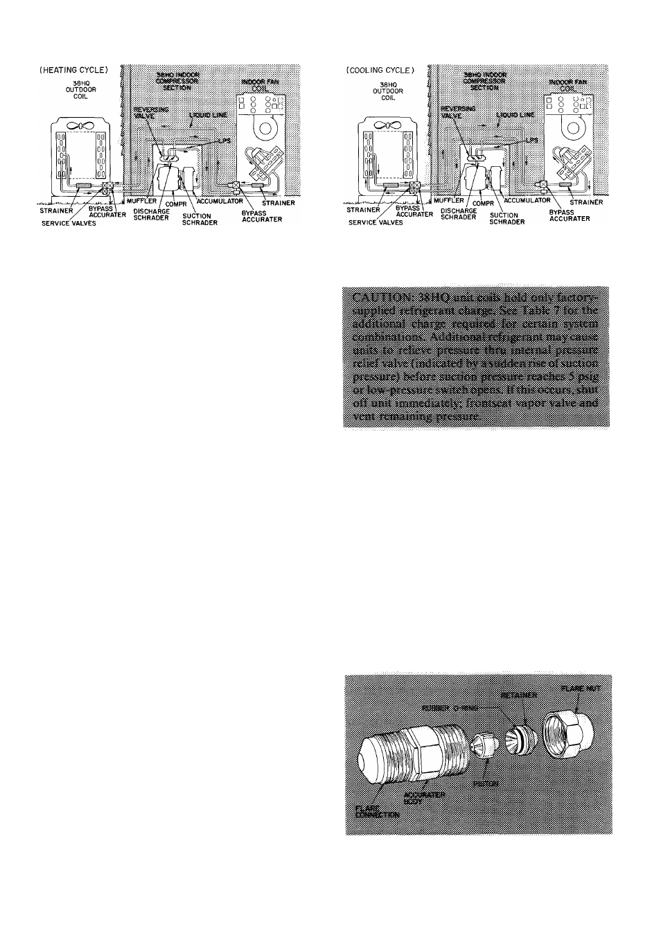
Fig. 25 — 38HQ Refrigerant Flow Diagrams
DEFROST
CONTROL,
consisting
of
a
defrost
timer, defrost thermostat and defrost relay, inter
rupts normal system heating operation every 90
minutes to defrost outdoor coil, if the coil saturated
suction
temperature
indicates
freezing
tempera
tures. Defrost control simultaneously stops outdoor
fan, energizes reversing valve solenoid to return
system to cooling cycle (outdoor eoil as condenser,
indoor
fan
coil
as
evaporator),
and
activates
accessory electric heater.
For the heat pump to defrost, 2 conditions are
necessary:
->1. Defrost timer switches LI from terminal 6 to
terminal 5.
2.
Refrigerant temperature from outdoor unit must
be cold enough to cause defrost thermostat con
tacts to close. Contacts close at 27 ( ± 4) F.
Every 90 minutes of elapsed running time the
defrost timer contacts close for 10 seconds. If the
defrost thermostat contacts are closed, the unit
defrosts. The defrost timer limits defrosting period
to 10 minutes. Normally the frost is removed and
the defrost thermostat eontacts will open to ter
minate defrosting before 10 minutes have elapsed.
Defrost thermostat contacts open at 80 F (± 6)
liquid refrigerant temperature. When defrosting is
terminated, the outdoor fan motor is energized and
reversing valve solenoid is de-energized returning
unit to heating cycle.
HEAT PUMP CIRCUITS shown in Fig. 25 are
refrigerant flow diagrams for heating and cooling
cycles.
Pumpdown Procedure (Cooling Cycle) — The
38HQ units may be pumped down in order to
make repairs on low side of system without losing
complete refrigerant charge.
1. Attach pressure gage to suetion service port.
2. Frontseat the liquid line valve on outdoor coil.
3. Start unit and run until suction pressure reaches
5 psig (see Caution) or low-pressure switch
opens.
4. Shut unit off and frontseat vapor line valve on
outdoor coil.
5. Vent remaining pressure.
AccuRater™ (Bypass Type) Servicing — See
Fig. 26 for bypass type AccuRater components. The
piston has a refrigerant metering hole thru it. The
retainer forms a stop for the piston in the refrig
erant bypass mode, and a sealing surface for liquid
line flare connection. To check, clean or replace
piston:
1. Shut off power to unit.
2.
Pump unit down using Pumpdown Procedure
described previously.
3.
Remove
liquid
line
flare
connection
from
AccuRater.
4.
Pull retainer out of body being careful not to
scratch flare sealing surface. If retainer does not
pull out easily, carefully use vise grips to
remove retainer.
Fig. 26 — AccuRater (Bypass Type)
Components
16