Carrier 38HQ User Manual
Page 10
Attention! The text in this document has been recognized automatically. To view the original document, you can use the "Original mode".
SERVICE
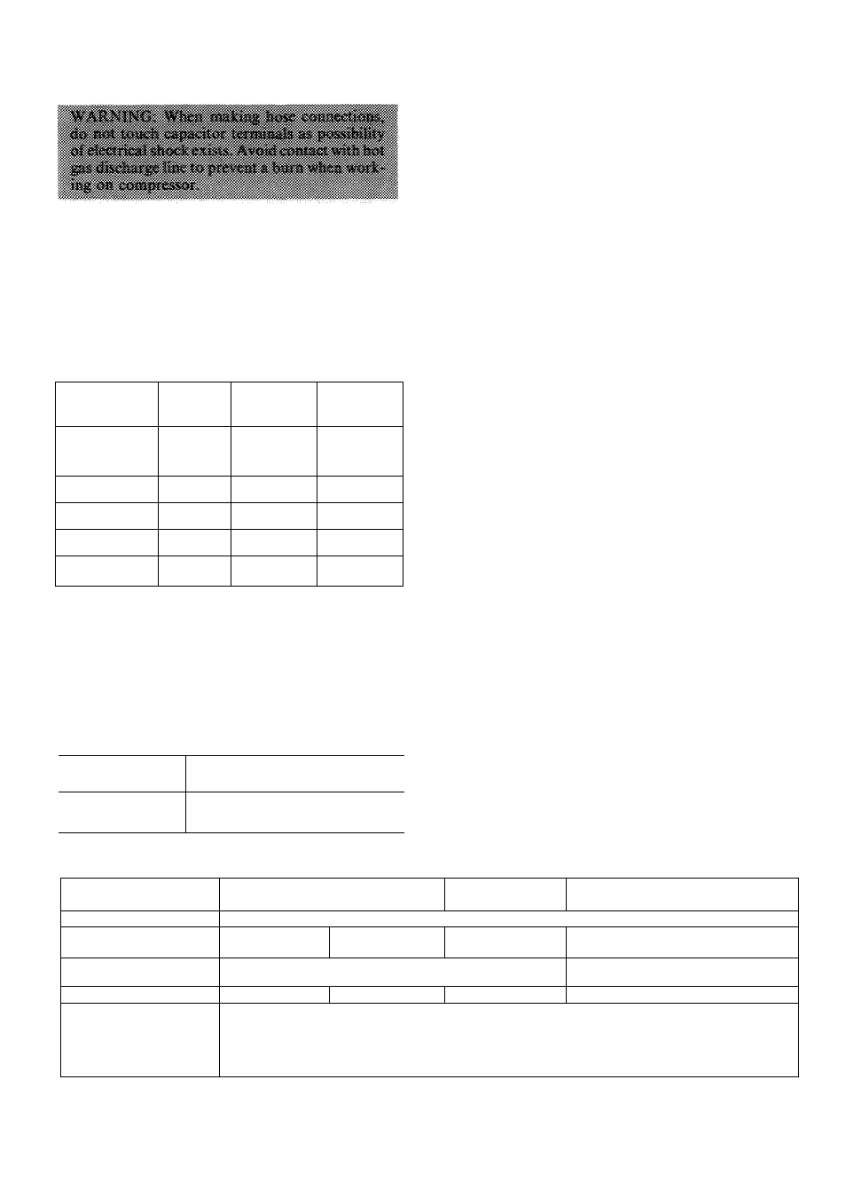
’■Refrigerant Charging — The 38HQ940 outdoor
coil contains a factory charge of 7.1 lb of R-22; the
38HQ960 outdoor coil contains a factory charge of
10.0 lb. This charge is correct for all systems except
those listed in Table 7. When the amount of refrig
erant shown in Table 7 is added, the final charge will
agree with the amount stamped on the compressor
section nameplate.
> Table 7 — Refrigerant Charging Data
INDOOR
COMPRESSOR
SECTION
OUTDOOR
COIL
INDOOR
FAN COIL
AMOUNT OF
R-22 TO BE
ADDED (oz)
38HQ120
38 H0940
40AQ030
28HQ.VQ030
40AQ036
28HQ,VQ036
I
7
7
15
15
38HQ127
38HQ940
40AQ036
28HQ,VQ036
8
8
38HQ134
38HQ940
28HQ,VQ036
40AQ036
14
14
38HQ140
38HQ960
28HQ,VQ042
40QB042
19
27
38HQ146
38HQ960
28HQ,VQ048
40QB048
19
27
The above charges are suited to systems with 25 ft
of recommended tubing. Adjust system charge for
refrigerant line lengths and diameters that differ
from 25 ft and 3/8-in. OD (liquid line), respectively,
using refrigerant weights shown in table below.
(Twenty-five feet of 3/8-in. OD tubing contains
14.4 oz of R-22.) Add R-22 charge to system if liquid
line is over 25 ft; remove charge if liquid line is
shorter than 25 feet.
LIQUID LINE
DIAM (in.)
OUNCES OF R-22/FT LENGTH
OF LIQUID LINE
3/8
58
5/16
36
1/4
21
When recharging is necessary during heating or
cooling season, weigh in total charge indicated in
Table 8. (Charge must be weighed in during heating
season.) Remove any refrigerant remaining in sys
tem before recharging. If system has lost complete
charge, evacuate system to 500 microns (29.7 in.
vacuum) before recharging. Service port connec
tions are provided on indoor compressor section
suction and discharge lines for evacuation and
charging. (See Fig. 24 for service port locations.)
Dial-a-charge
charging
cylinder
is
an
accurate
device used to recharge systems by weight. These
cylinders are available at refrigeration supply firms.
To check and/or adjust charge during cooling
season, use correct Cooling Cycle Charging Chart
(Fig. 10 thru 16) and follow Charging Chart Method
below. The charging chart may also be used as an
alternate method of recharging system.
To check system operation during heating cycle,
use correct Heating Cycle Operation Check Chart
(Fig. 17 thru 23). These charts indicate whether a
correct relationship exists between system operating
pressures and air temperatures entering indoor and
outdoor units. If pressure and temperature lines do
not intersect on chart, the system refrigerant charge
may not be correct or other system abnormalities
may exist. Do not use Operation Check Charts to
adjust refrigerant charge. Weigh charge into system.
COOLING CYCLE CHARGING CHART
METHOD
1. Operate unit a minimum of 10 minutes before
checking
charge,
and
after
each
charge
adjustment.
2. Measure suction pressure by attaching a gage to
indoor unit suction service port. (See Fig. 24 for
correct service port location.)
3.
Measure outdoor (coil inlet) air dry-bulb tem
perature with service thermometer.
4.
Using a sling psychrometer, measure wet-bulb
temperature of air entering indoor fan coil.
5.
Refer to correct Charging Chart. Locate on
curves where outdoor air dry-bulb and indoor air
wet-bulb temperature lines intersect.
'-N
Table 8 — Service Data
INDOOR COMPR
SECTION 38HQ
120 j 127
134
140 146
REFRIG
R-22
COMPR MODEL*
Oil Rechg (oz)
MD2013HB
46
MD2713HB
46
MD3413HB
46
PC4616AD ! PC5316AD
76 1 76
OUTDOOR
COIL
38 H0940
38HQ960
R-22 CHG (lb)t
7 5
7.1t
7 1
100
FAN
Cfm
Rpm
Diameter (in.)
Motor Hp
Propeller — Direct Drive
3100 1 3600
1015 1080
20 20
1/5 1/4
*Refer to Service Parts catalog for replacement compressor model numbers
fFactory-supplied charge in outdoor unit for complete system Charge adjustment may be required on some systems See Table 7
783
10