Carrier 38HQ User Manual
Page 7
Attention! The text in this document has been recognized automatically. To view the original document, you can use the "Original mode".
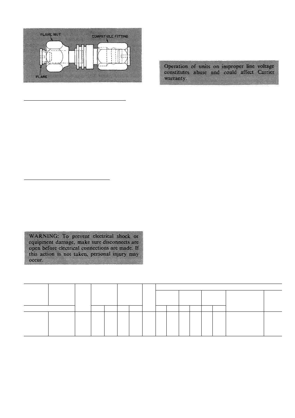
Fig. 7 — Accessory Coupler
Sweat
Connection
to
Compatible
Fitting
(Use
refrigerant grade tubing.)
1. Remove locking nut, rubber O-ring and Schrader
core from valve.
2. Cut tubing to correct length.
3.
Insert tube into Compatible Fitting. Wrap top
and bottom of service valves in wet cloth to
prevent damage by heat. Solder with low-
» temperature (430 F) silver alloy solder.
4. Replace Schrader core.
5.
Evacuate or purge system with field-supplied
refrigerant.
Accessory Flare-to-Compatible Coupler is shown in
Fig. 7. Attach flare nut on coupler to flare fitting on
unit liquid line connection. Connect liquid line to
Compatible
Fitting
using
mechanical
or
sweat
connection. When mechanical connection is made,
use 2 wrenches when tightening Compatible Fitting
nut — one to hold coupler and one to tighten nut.
Liquid line must be flared if coupler is not used.
Step 5 — Make Electrical Connections
Field wiring must comply with local and national
fire, safety and electrical codes. Voltage to units
must be within ± 10% of voltage indicated on
nameplate. Contact local power company for cor
rection of improper line voltage.
When
making
electrical
connections,
provide
clearance at unit for refrigerant piping connections.
See Table 5 for recommended wire and fuse sizes.
Line and control power wiring for 38HQ outdoor
coil are from connections in the 38HQ compressor
section. Line power wire size to outdoor coil section
must be 14 gage minimum when total wire length
connecting compressor section to coil is under 25
feet. If over 25 ft, use same wire size as compressor
section branch circuit.
INSTALL A BRANCH CIRCUIT DISCONNECT
per NEC of adequate size to handle compressor
section starting current. Provide a separate discon
nect switch for outdoor coil section. Provide a
separate disconnect per NEC for indoor fan coil and
for each accessory electrie heater circuit as required.
(See Indoor Unit and Electric Heater Installation,
Start-Up
and
Serviee
Instructions.)
Locate
dis-
connect(s) within sight of and readily accessible to
the unit, per section 440-14 of National Electrical
Code (NEC).
BRING
LINE
POWER
LEADS
INTO
COM
PRESSOR SECTION — Extend leads from dis
connect per NEC thru 1-1/8in. hole provided in
compressor section top panel (Fig. 2) and into eon-
trol box. Extend line power leads for outdoor eoil
section thru 7/8-in. hole provided in compressor
section top panel and into control box.
Table 5 — Electrical Data (60-Hz)
INDOOR
COMPR
SECTION
OUTDOOR
COIL
V/PH
OPER
VOLTAGE*
COMPR
OFM
FLA
BRANCH CIRCUIT
Min Wire
Size
(AWG)t
Max Ft
Wire
Min Gnd
Wire
Sizef*
Max Fuse or
HACR Type
Ckt Brk Ampstt
MCA
38HQ
Max
Min
LRA
RLA
ICS
OC
ICS
OC
ICS
OC
120
940
65
103
1 5
12
50
20
164
127
940
72
17 1
1 5
10
50
40
22 7
134
940
230/1
254
207
88
20 0
1 5
10
14t
43
25t
10
14t
45
26 7
140
960
94
21 7
2 3
8
58
50
30 7
146
960
106
27 9
2 3
8
50
60
37 2
AWG — American Wire Gage
FLA — Full Load Amps
HACR — Heating, Air Conditioning & Refrigeration
ICS
— Indoor Compressor Section
LRA
— Locked Rotor Amps
MCA — Minimum Circuit Amps
OC
— Outdoor Coil
OFM
— Outdoor Fan Motor
RLA
— Rated Load Amps
‘Permissible limits of the voltage range at which the unit will
operate satisfactorily
fCopper wire sizes based on 60C Use copper or copper-clad
aluminum wire only Use latest NEC for copper-clad aluminum
conductor sizing
^Required when using non-metallic conduit
“Outdoor Coil Wiring — For 25-ft wire run or less, use minimum
14 AWG wire size For longer wire run, use same size wire as
supply to compressor section
ttMaximum dual element size
NOTE All units have 24-v control circuit which requires external
power source