Carrier 38HQ User Manual
Page 17
Attention! The text in this document has been recognized automatically. To view the original document, you can use the "Original mode".
5. Slide piston out by inserting a small soft wire
thru metering hole (18-gage thermostat wire).
See that metering hole, sealing surface around
piston cones and fluted portion of piston are
,
not damaged.
I
6. Clean piston refrigerant metering hole.
7.
Replace
retainer
O-ring
before
reassembling
bypass type AccuRater™. Carrier O-ring part no.
is 99CC501052.
LIQUID
LINE
STRAINER
protects
AccuRater.
Made of wire mesh, it is located in the liquid line
inside indoor fan coil behind liquid line service
valve (Fig. 25). Liquid line is belled and sweat
connected where strainer is located. If strainer is
plugged, unsweat belled liquid line connection and
replace strainer.
MAINTENANCE
Lubrication
COMPRESSOR contains factory oil charge. Re
place oil when lost. See Table 8 for oil recharge.
If necessary, refer to Carrier Standard Service Tech
niques Manual, Chapter 1, page 1-21, for oil
recharging procedure. Use Carrier PP33-1, Texaco
Capella B or Suniso 3G oil.
OUTDOOR FAN MOTOR BEARINGS are pre
lubricated for 3 years heavy duty or 5 years normal
duty. When lubrication is necessary, send motor to
authorized motor repair shop.
Outdoor Coil Cleaning — Ensure power to unit is
shut off. Clean the outdoor coil with water at the
beginning of every cooling season or more often if
required. Use ordinary garden hose at a pressure
high enough to clean efficiently. For best results, un
screw and remove unit top cover (grille).
Insert hose nozzle between fan blades and spray
coil fins from inside-to-outside the unit. If unit has
a double-row coil, loosen screws to separate coils,
pull outer row of coils away from inner row, and
flush dirt toward outside of both coils. Flush dirt
from basepan by spraying water thru top of unit.
Avoid splashing mud on coil or water on the fan
motor. Make sure that water drainage holes under
outdoor coil are not obstructed.
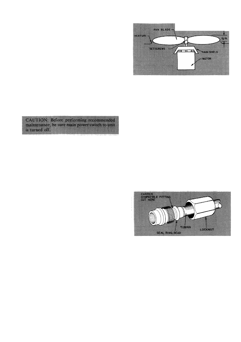
Outdoor Fan Position — Required fan position is
shown in Fig. 27. Adjust fan by loosening setscrews
and moving fan blades up or down.
FAN MOTOR REMOVAL
1. Shut off power to outdoor coil.
2. Remove unit top cover (grille). Open or remove
service door. Remove junction box cover.
3. Disconnect fan motor leads in line-voltage
section of junction box. See Fig. 24.
Fig. 27 — Outdoor Fan Position
4.
Remove fan from motor shaft by loosening
setscrews and pulling upward on fan hub.
5.
Remove bolt holding fan motor to motor
mounting bracket. Remove motor with wiring
thru top of unit.
To replace motor: place motor on self-positioning
motor mounting bracket and retighten bolt.
Before replacing metal fan, be sure rain shield
>(Fig. 27) is in place on motor shaft. Seal with
Permagum around hub to prevent entry of water
between hub and shaft.
Compatible Fitting Repair
LEAKING
MECHANICAL
CONNECTION
—
Frontseat outdoor section service valves and relieve
refrigerant
pressure
in
tubing
and
compressor
section.
Back
locknut
off
Carrier
Compatible
Fitting
onto
tube.
Cut
fitting
between
threads
and seal ring bead shown in Fig. 28. Remove tubing
section remaining in threaded portion of fitting.
Discard locknut.
Fig. 28 — Carrier Compatible Fitting
Clean, flux, and insert new tube end into remain
ing portion of Carrier Compatible Fitting. Wrap
valve base (outdoor unit) in wet rag. Heat and apply
Tow-temperature solder (430 F).
LEAKING
SWEAT
CONNECTION
—
Frontseat
service
valves
and
relieve
refrigerant
pressure
in tubing. Clean and flux area around leak and apply
- low-temperature solder (430 F).
Evacuate or purge indoor fan coil, compressor
section and tubing system. Add refrigerant charge
(see charging instructions).
LEAKING
FLARE
CONNECTION
—
Cut
and
reflare 3/8-in. system liquid line.
17