A caution – Carrier 51CM User Manual
Page 9
Attention! The text in this document has been recognized automatically. To view the original document, you can use the "Original mode".
Remove fan motot leads irorn wiie ties Identify
wires foi coirect reassembly
Remove fan motoi ground wiie fiom partition
assembly by lemoving one sciew
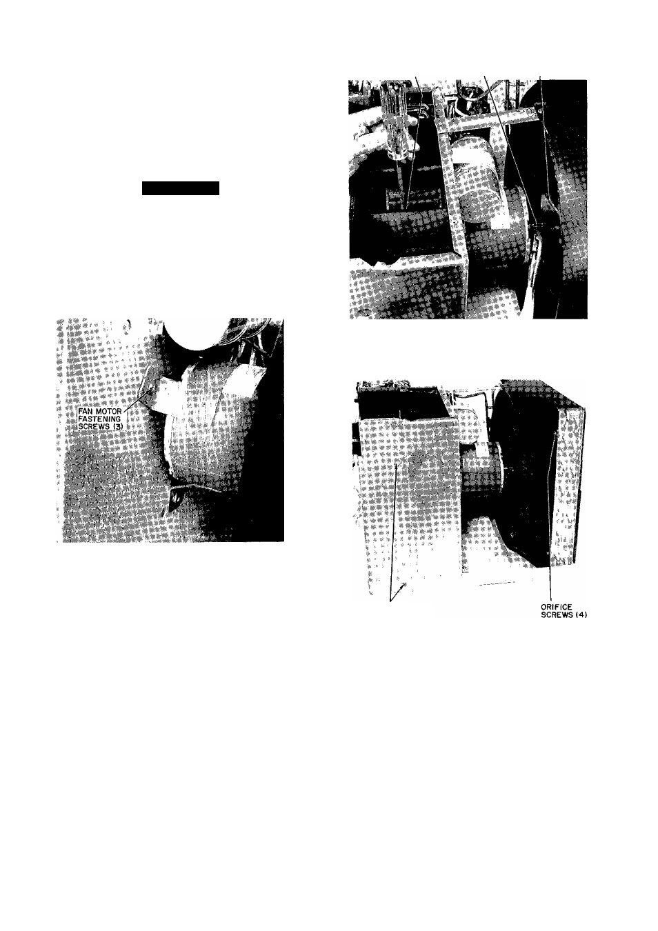
Remove 3 screws fastening fan motoi to partition
assembly See Fig 13
Pull fan motor carelully towaid condenser coil
and remove
A CAUTION
Be careful to avoid damaging condensei coil
when pulling and lemoving fan motor
SET SCREW LOCATION FAN CLIP
CONDENSER FAN
h Reverse above proceduie foi leassembly of fan
motoi
NOTE For proper orientation ol diain holes in re
placement motor, check to be suie motor label is
facing up Foi optimum perfoi mance, position blowei
wheel and propeller fan properly on motoi shaft
Fig. 13 — Fan Motor
FAN MOTOR LUBRICATION — Fan motor is factory
lubiicated and requires no lubrication undei normal con
ditions foi a period of 5 years The fan motor should be
oiled at the beginning of each cooling season thereafter
li the unit is subjected to heavy usage, dusty atmosphere,
or other abnormal conditions, oil motor at the beginning
of the first cooling season and each cooling season
theieaftei
Fan motois have an oil port on each end ol the motoi
Remove the lubber dust plugs liom oil poits and add 4
diops of SAE 20 oil through each poit Be sure to replace
plugs aftei oiling
14 Condenser Fan—See Condensei Fan in Fig 14
a To aid in leassembly, maik shaft at point wheie
hub and shaft meet
b Remove clip from condensei tan as shown in
Fig 14
c Remove condenser oiifice by lemoving 4 screws
holding condenser orifice to the tube sheet as
shown in Fig 15 and 18
Fig. 14 — Blower Set Screw and
Condenser Fan Clip
PARTITION
ASSEMBLY SCREWS
Fig 15 — Partition and Orifice Assembly Screws
d Remove 2 sciews in back of unit as shown in
Fig 16 Carefully lift and pull condensei coil
outwaid
e Reverse above procedure foi reassembly
15 Evaporator Blower — See Evaporatoi Blowei in
Fig 14
Remove 3 screws in fiont ol unit as shown in
Fig 17
Remove one screw oncompressoi side (see Fig 16)
which holds evaporator coil tube sheet to partition
assembly
Remove 2 side seiews lastening pai tition assembly
to basepan and paitition assembly to evapoiator
coil tube sheet See Fig 15
Remove 2 back sciews which hold partition
assembly to basepan See Fig 15