Carrier 51CM User Manual
Page 17
Attention! The text in this document has been recognized automatically. To view the original document, you can use the "Original mode".
c Cut interconnecting tubing and lemove 2 screws
securing condenser coil Remove condenser
orifice mounting screws (4)
d Remove condenser coil
e Reverse procedure for reassembly
43 Strainer — Strainer is installed in the interconnect
ing tubing between the condenser and the capillary
tube To change strainer
a Purge and remove all refrigerant from system
b Cut tubing one in horn capillary tube insertion
point
c Use a thin piece of wire to remove strainer from
tubing
d Insert new strainer into tubing Reassemble with a
field-supplied 1/4-in copper coupling
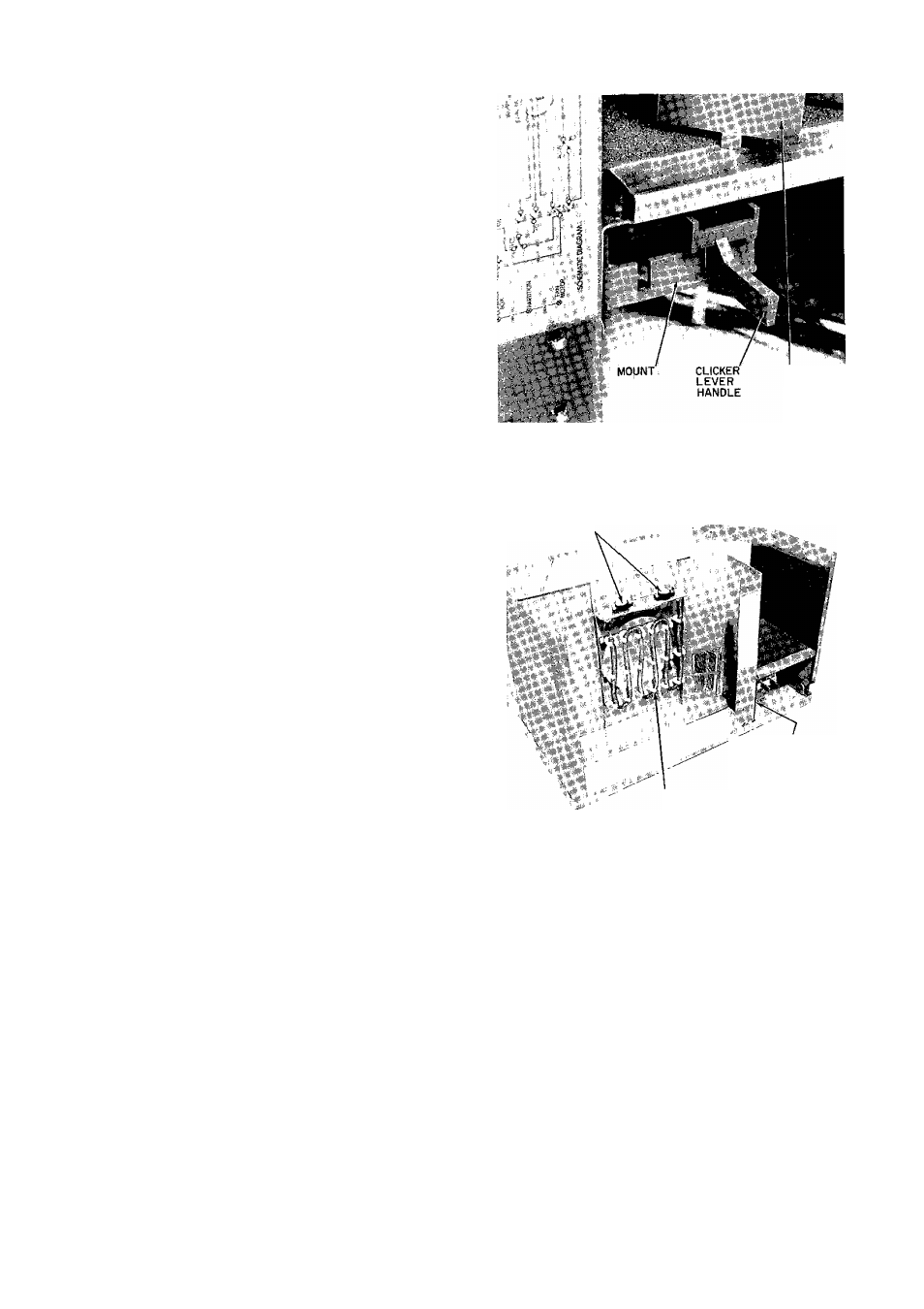
44 Vent and Exhaust Linkage — See Vent and
Exhaust Linkage in Fig 31
a Remove decorative front grille Refer to Grille
instructions and Fig 26
b Remove control box Refer to Control Box in
structions and Fig 25
c Remove clicker lever Push up on lever handle
while holding mount down See Fig 34
d To reinstall, push clicker lever straight in through
mount, until it snaps in place
e To remove mount, remove 2 screws Irom mount
and remove from discharge deck
1 To remove push bars, remove screws and dis
assemble from discharge deck See Fig 31
g To reassemble, reverse above procedure
45
Electric Heater Assembly — See Electric
Heater in Fig 35 The electric heater is found only
in the Models 5ICV and 51 GY
a Remove chassis from casing See Chassis instruc
tions and Fig 29
b Remove partition top cover by removing4 screws
c Remove 2 wires Itom heater assembly Mark wires
to aid in reassembly
d Repair or replace limit switches as needed
e Remove heater by removing 2 screws and lifting
straight up
f Reverse above procedure for reassembly
DISCHARGE
LOUVER
Fig 34 — Vent and Exhaust Linkage
LIMIT SWITCHES
DISCHARGE
DECK SCREW
(NOT VISIBLE)
ELECTRIC HEATER
Fig. 35 — Electric Heater Assembly
17