Fig. 8 — control wiring connections, Step 6 — adjust evaporator-fan speed — adjust, Table 3 — heat anticipator settings – Carrier 50LJ008-014 User Manual
Page 9
Attention! The text in this document has been recognized automatically. To view the original document, you can use the "Original mode".
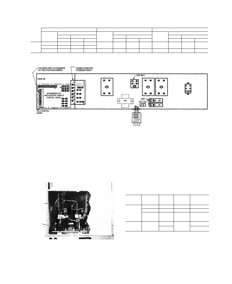
Table 3 — Heat Anticipator Settings
UNIT VOLTAGE
208/230
460
575
UNIT
Configuration
Configuration
Configuration
Heater kW
1 Stage
2 Stage
Heater kW
1 Stage
2 Stage
Heater kW
1 Stage
2 Stage
Stage 1
Stage 1
Stage 2
Stage 1
Stage 1
Stage 2
Stage 1
Stage 1
Stage 2
104, 160
03
NA
NA
139, 165
03
NA
NA
18 0, 36 0
0.3
NA
NA
50LJ
32 0, 24 8
06
0.3
03
27 8, 33 0
42 4, 50 0
0 9
06
03
41 7, 50 0
06
03
03
54.0
0.6
03
03
THERMOSTAT CONNECTIONS
THERMOSTAT
LEGEND
BAT
- Battery
C
— Contactor
DAT
— Discharge-Air Thermistor
EWIC/EMFC
— Energy Management Closed
EMO/EMFO
—
Energy Management Open
EQUIP
— Equipment
GND
— Ground
IFC
— Indoor-Fan Contactor
THREE-PHASE
POWER SUPPLY
IFR
— Indoor-Fan Relay
OFC
— Outdoor (Condenser) Fan Contactor
P
— Plug
TB
— Terminal Block
TRAN
— Transformer
---------- Field Wiring
Factory Wiring
Fig. 8 — Control Wiring Connections
RACEWAY-
HOLE IN
END PANE!
(HIDDEN)
Fig. 9 — Field Control Wiring Raceway
Step 6 — Adjust Evaporator-Fan Speed — Adjust
evaporator-fan speed to meet jobsite conditions.
For units with electric heating, required minimum cfm is
2250 for 50LJ008; 2550 for 50LJ009; and 3000 for 50LJ012
and 014 with the following exceptions.
UNIT
UNIT
VOLTAGE
HEATER
kW
UNIT
CONFIG-
ATION
REQUIRED
MINIMUM
CFM
208/230
42 4
Horizontal
3200
50LJ012
and 014
208/230
50.0
Horizontal
3200
460
50.0
Horizontal
or
Vertical
3200
50LJ008-
575
180
Horizontal
or
Vertical
2800
014
36 0
2350
Table 4 shows fan rpm motor pulley settings, Table 5
shows motor efficiencies and Table 6 gives accessory static
pressure drops. Refer to Tables 7-12 to determine fan speed
settings. Fan motor pulleys are factory set for speed shown
in Table 1.