Operating sequence, A caution – Carrier 50LJ008-014 User Manual
Page 16
Attention! The text in this document has been recognized automatically. To view the original document, you can use the "Original mode".
Operating Sequence
SERVICE
COOLING, UNITS WITHOUT ECONOMIZER - When
thermostat calls for cooling, terminals G and Y1 are ener
gized. The indoor (evaporator) fan contactor (IFC), and com
pressor contactor no. 1 (Cl) are energized and evaporator-
fan motor, compressor no. 1 and condenser fan start. The
condenser-fan motor runs continuously while unit is cool
ing. If the thermostat calls for a second stage of cooling by
energizing Y2, compressor contactor no. 2 (C2) is ener
gized and compressor no. 2 starts.
HEATING, UNITS WITHOUT ECONOMIZER (If Acces
sory Heater is Installed) — Upon a call for heating through
terminal Wl, IFC and heater contactor no. 1 (HCl) are en
ergized. On unit equipped for 2 stages of heat, when addi
tional heat is needed HC2 is energized through W2.
COOLING, UNITS WITH ACCESSORY ECONOMIZER
— When the outdoor-air temperature is above the OAT
(outdoor-air thermostat) setting and the room thermostat calls
for cooling, compressor contactor no. 1 is energized to start
compressor no. 1 and the condenser-fan motor. The evaporator-
fan motor is energized and the economizer damper moves
to the minimum position. Upon a further call for cooling,
compressor contactor no. 2 will be energized, starting com
pressor no. 2. After the thermostat is satisfied, the damper
moves to the fully closed position.
When the outdoor-air temperature is below the OAT set
ting and the thermostat calls for cooling, the economizer
dampers move to the minimum position. If the discharge-
air temperature is above 54 F, the damper continues to open
until it reaches the fully open position. (The damper will
open for 5 seconds and remain stationary for 30 seconds
during this period.)
When the discharge-air temperature falls to between 54 F
and 50 F, the damper will remain at an intermediate open
position. If the discharge-air temperature falls below 50 F,
the damper will modulate back to the minimum position.
When the thermostat is satisfied, the damper will move to
the fully closed position.
If the outdoor air alone cannot satisfy the cooling require
ments of the conditioned space, economizer cooling is in
tegrated with mechanical cooling, providing second-stage
cooling. Compressor no. 1 and the condenser fan will be
energized and the position of the economizer damper will
be determined by the discharge-air temperature. Compres
sor no. 2 is locked out.
When the second stage of cooling is satisfied, the com
pressor and condenser-fan motor will be deenergized. The
damper position will be determined by the discharge-air
temperature.
When the first stage of cooling is satisfied, the damper
will move to fully closed position.
HEATING, UNITS WITH ACCESSORY ECONOMIZER
(If Accessory Heater is Installed) — When the room ther
mostat calls for heat through terminal W1, the evaporator-
fan contactor and heater contactor no. 1 are energized. On
units equipped for 2 stages of heat, when additional heat is
needed, heater contactor no. 2 is energized through W2.
The evaporator-fan motor is energized 45 seconds after heat
ing begins, and the economizer damper moves to the min
imum position. When the thermostat is satisfied, the damper
moves to the fully closed position.
A CAUTION
When servicing unit, shut off all electrical power to
unit to avoid shoek hazard or injury from rotating parts.
Clssning
Inspect unit interior at the beginning of each
heating and cooling season or as operating conditions
require.
EVAPORATOR COIL
1. Turn unit power off. Remove evaporator coil access panel.
2. If accessory economizer is installed, remove eeono-
mizer by disconnecting Molex plug and removing econ
omizer mounting screws. Refer to Accessory Economizer
Installation Instructions for more details.
3. Slide filters out of unit.
4. Clean coil using a commercial coil cleaner or dish
washer detergent in a pressurized spray canister. Wash
both sides of coil and flush with clean water. For best
results, backflush toward return-air section to remove
foreign material.
5. Flush condensate pan after completion.
6. Reinstall economizer and filters.
7. Reconnect wiring.
8. Replace access panels.
CONDENSER COIL — Inspect coil monthly. Clean con
denser eoil annually, and as required by location and outdoor-
air conditions.
Two-Row Coils — Clean coils as follows:
1
.
2
.
3.
4.
5.
Turn off unit power.
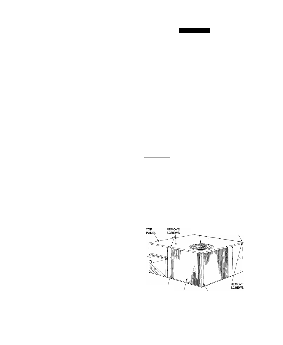
Remove top panel screws on condenser end of unit.
Remove condenser coil comer post. See Fig. 12. To hold
top panel open, place coil corner post between top panel
and center post. See Fig. 13.
Remove device holding coil sections together at return
end of condenser coil. Carefully separate the outer coil
section 3 to 4 in. from the inner coil section. See
Fig. 14.
Use a water hose or other suitable equipment to flush
down between the 2 coil sections to remove dirt and de
bris. Clean the outer surfaces with a stiff brush in the
normal manner.
CONDENSER
FAN
CONTROL BOX
CORNER POST
COIL CENTER
POST
i
CONDENSER
COIL
REMOVE COIL
CORNER POST
Fig. 12 — Cleaning Condenser Coil
i
16