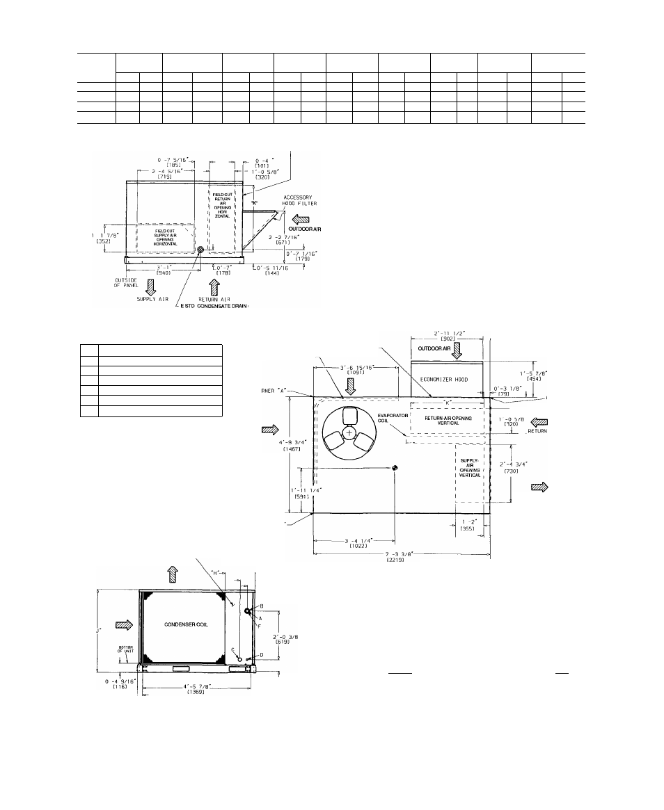
Fig. 6 - base unit dimensions – Carrier 50LJ008-014 User Manual
Page 6
Attention! The text in this document has been recognized automatically. To view the original document, you can use the "Original mode".
UNIT
STD. UNIT
WEIGHT
ECONOMIZER
WEIGHT
CORNER
WEIGHT (A)
CORNER
WEIGHT (B)
CORNER
WEIGHT (C)
CORNER
WEIGHT (D)
“H”
“J
“K”
Lb
Kg
Lb
Kg
Lb
Kg
Lb
Kg
Lb
Kg
Lb
Kg
Ft-ln.
mm
Ft-ln.
mm
Ft-in.
mm
50LJ008
755
342
44
20
164
74
140
64
208
94
243
110
2-0%
632
3-5¥i6
1050
2-9"/ie
856
50LJ009
760
345
44
20
165
75
141
64
209
94
245
111
1-2%
378
3-5¥ie
1050
2-9”/i6
856
50U012
915
415
44
20
199
90
170
77
252
114
294
134
1-2%
378
4-1 yi 6
1253
3-0%
924
50U014
930
422
44
20
202
92
172
78
256
116
300
136
1-2%
378
4-15/16
1253
3-0%
924
FILTER ACCESS PANEL
(DISPOSABLE FILTERS)
NOTES:
1 Dimensions in [ ] are in millimeters
Center of gravity
3 Direction of airflow
4 On vertical discharge units, ductwork to be attached to accessory roof curb
only For horizontal discharge units, field-supplied flanges should be af-
tached fo horizontal discharge openings and all ductwork should be at
tached to the flanges.
5 Minimum clearance (local codes or jurisdiction may prevail):
a Bottom to combustible surfaces (when not using curb) zero in on ver
tical discharge units, and one in on horizontal discharge units,
b. Condenser coil, for proper airflow, 36 in. one side, 12 in. the other The
side getting the greater clearance is optional
c Overhead, 60 in to assure proper condenser fan operation
d Horizontal supply and return end, zero inches,
e Between units, control box side, 42 in per NEC
f Between unit and ungrounded surfaces, control box side, 36 in. per NEC
g Between unit and block or concrete walls and other grounded surfaces,
control box side, 42 in per NEC
6 With the exception of the clearance for the condenser coil as stated in Notes
5b and c, a removable fence or barricade requires no clearance
7 Units may be installed on combustible floors made from wood or class A,
B, or C roof covering material.
R I G H T S I D E
R E A R
CONNECTION SIZES
A
1%" dia [35] field power supply hole
B
2y2” dia [64] power supply knockout
C
1%" dia [44] charging-port hole
D
%" dia [22] field control wiring hole
E
%”-14 NPT condensate drain
F
2" dia [51] power supply knockout
0'-3 9/16'
C90J
FILTER/ECONOMIZER ACCESS PANEL
CONDENSER COIL
,__ , 0 -5 1/2
]
i_ [140]
AIR
L E F T S I D E
ELECTRICAL
DISCONNECT LOCATION
0'-7 3/8
■ [187]
- 0 -3 13/16'
[97]
SUPPLY AIR
"L 0'-5 7/16'
\H38]
0'-3 1/8' ^CORNER 'C'
[79]
F R O N T
O'-O 3/8'
[
1 0
]
CONTROL BOX AND
COMPRESSOR ACCESS PANEL
ÍB©©
EVAPORATOR-FAN MOTOR,
BLOWER AND ELECTRIC
HEAT ACCESS PANEL
0'-5 3/4'
[146]
FORK LIFT SLOTS
©B
r
0'-2 9/16^
[65] TYP
0'-2 1/4' [57]
(TYP 8 PLACES)
L E F T S I D E
Fig. 6 - Base Unit Dimensions
F R O N T
t