Fig. 3 — unit leveling tolerance, A caution, Fig. 5 — rigging details – Carrier 50LJ008-014 User Manual
Page 4
Attention! The text in this document has been recognized automatically. To view the original document, you can use the "Original mode".
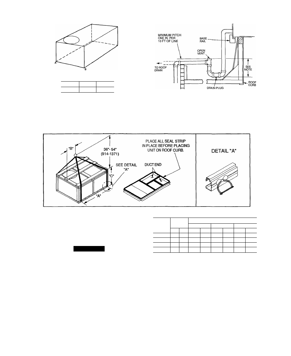
MAXIMUM ALLOWABLE
DIFFERENCE (in.)
A-B
B-C
A-C
0.5
1 0
1 0
Fig. 3 — Unit Leveling Tolerance
NOTE: Trap should be deep enough to offset maximum unit static
difference. A 4-in trap is recommended.
Fig. 4 — External Trap Condensate Drain
NOTES-
1 Dimensions in ( ) are in miiiimeters
2. Hook rigging shackles through holes in base rail, as shown in
detail “A” Holes in base rails are centered around the unit cen
ter of gravity. Use wooden top skid when rigging to prevent rig
ging straps from damaging unit
3. Unit weights do not include economizer. See Table 1 for econ
omizer weights.
A CAUTION
All panels must be in place when rigging
MAX
DIMENSIONS
UNIT
WEIGHT
“A”
“B”
“C”
lb
kg
in.
mm
in.
mm
in.
mm
50LJ008
755
342
77 42
1967
40 25
1022
41.31
1050
50LJ009
760
345
77.42
1967
40 25
1022
41.31
1050
50LJ012
915
415
77.42
1967
40.25
1022
49.31
1253
50LJ014
930
422
77.42
1967
40 25
1022
49.31
1253
Fig. 5 — Rigging Details
t