Lubrication, Condenser-fan adjustment (fig. 15) – Carrier 50LJ008-014 User Manual
Page 17
Attention! The text in this document has been recognized automatically. To view the original document, you can use the "Original mode".
COIL CORNER
CENTER BAFFLE
TOP PANEL
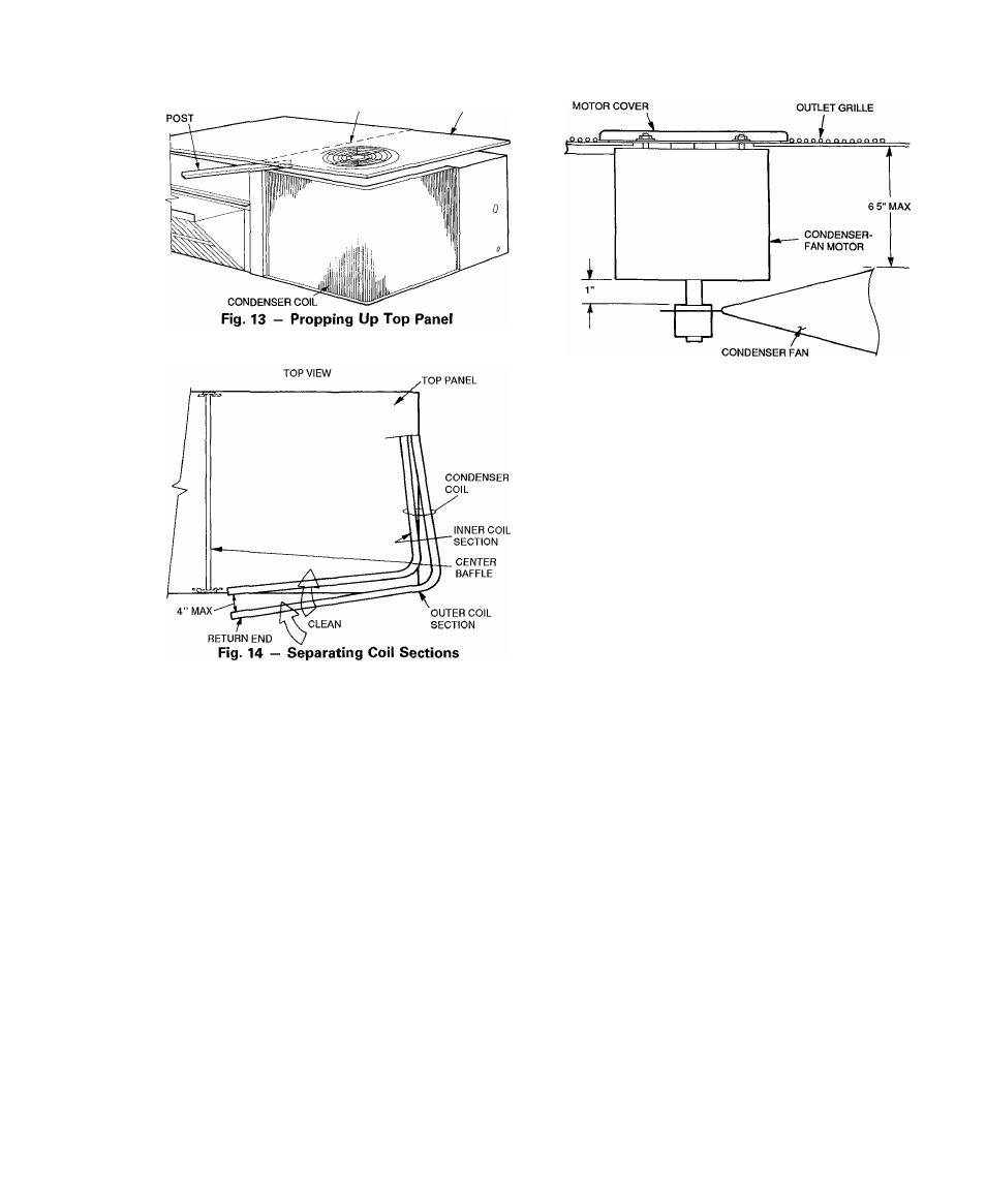
6. Reposition the outer coil section and remove the coil
corner post between the top panel and center post. Se
cure the sections together. Install the coil comer post
and coil center post, and replace all screws.
CONDENSATE DRAIN — Check and clean each year at
start of cooling season. In winter, keep drain dry or protect
against freeze-up.
FILTERS — Clean or replace at start of each heating and
cooling season, or more often if operating conditions re
quire it. Replacement filters must be same dimensions as
original filters.
Lubrication
COMPRESSORS — Each compressor is charged with cor
rect amount of oil at the factory.
FAN-MOTOR BEARINGS — Fan-motor bearings are of
the permanently lubricated type. No further lubrication is
required. No lubrication of condenser- or evaporator-fan
motors is required.
Condenser-Fan Adjustment (Fig. 15)
1. Shut off unit power supply.
2. Remove condenser-fan assembly (grille, motor, motor
cover and fan) and loosen fan hub setscrews.
3. Adjust fan height as shown in Eig. 15.
4. Tighten setscrews.
5. Replace condenser-fan assembly.
Fig. 15 — Condenser-Fan Adjustment
Refrigerant Charge — Amount of refrigerant charge
is listed on unit nameplate (also refer to Table 1). Refer to
Carrier Standard Service Techniques Manual, Chapter 1,
Refrigerants section.
Unit panels must be in place when unit is operating dur
ing charging procedure.
NO CHARGE — Use standard evacuating techniques. Af
ter evacuating system, weigh in the specified amount of re
frigerant (refer to Table 1).
LOW CHARGE COOLING — Use Cooling Charging Charts,
Fig. 16-19. Vary refrigerant until the conditions of the ap
propriate chart are met. Note the charging charts are differ
ent from type normally used. Charts are based on charging
the units to the correct superheat for the various operating
conditions. Accurate pressure gage and temperature sens
ing device are required. Connect the pressure gage to the
service port on the suction line. Mount the temperature sens
ing device on the suction line and insulate it so that outdoor
ambient temperature does not affect the reading. Indoor-air
cfm must be within the normal operating range of the unit.
TO USE COOLING CHARGING CHARTS - Take the
outdoor ambient temperature and read the suction pressure
gage. Refer to appropriate chart to determine what suction
temperature should be. If suction temperature is high, add
refrigerant. If suction temperature is low, carefully blow
some of the charge. Recheck the suction pressure as charge
is adjusted.
Example: (Fig. 16)
Outdoor Temperature.........................................................85 F
Suction Pressure............................................................70 psig
Suction Temperature should be......................................... 42 F
(Suction Temperature may vary ±5° F.)
If Chargemaster® charging device is used, temperature
and pressure readings must be accomplished using the charg
ing charts.
17