Carrier 50CD/CH User Manual
Page 9
Attention! The text in this document has been recognized automatically. To view the original document, you can use the "Original mode".
THERMOSTAT ASSEMBLY
LOW-VOLTAGE THERMOSTAT CONNECTIONS IN UNIT CONTROL BOX
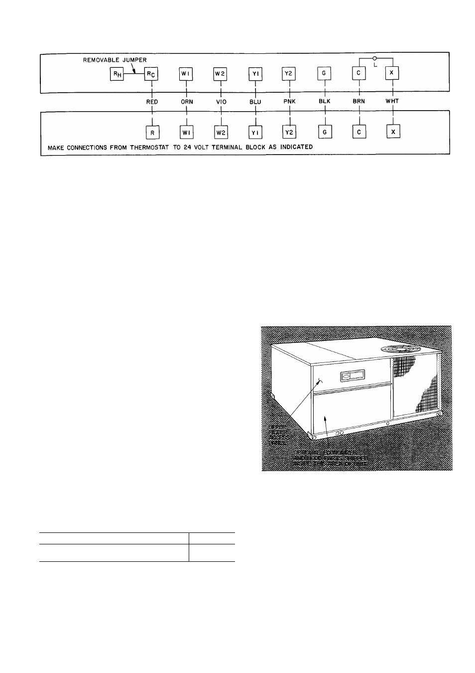
Fig. 12 — Field Control Thermostat Wiring
•#
Unit failure as a result of operation on improper
line voltage or excessive phase imbalance constitutes
abuse and may cause damage to electrical compo
nents. Such operation would invalidate any appli
cable Carrier warranty.
UNITS WITH ELECTRIC HEAT — When elec
tric heat is installed, connect the field power wires
to terminal block located in the single point box.
The single point box is attached to the corner post,
directly below the control box.
DISCONNECTS — A fused disconnect is required
only on units without electric heat. When electric
heat is installed, use a NEC disconnect of adequate
size. Provide fusing for disconnect if required by
local codes. The unit informative nameplate and
Table 2 list electric heat fuse and wire amperage.
Field Control Wiring — Install a Carrier-approved
accessory thermostat assembly according to instal
lation instructions included with accessory. Locate
thermostat assembly on a solid wall in the condi
tioned space to sense average temperature.
THERMOSTAT WIRES — Use 18 gage for 0- to
50-ft long wires, 16 gage for 50- to 75-ft wire
lengths. Route the control wires thru hole provided
in the corner post (see Fig. 3 and 4) and then feed
wires thru a raceway built into the corner post.
Route wires from the raceway into the 24-v barrier
located on the left side of the control box. Make
connections as shown in Fig. 12.
Set heat anticipator settings as indicated below.
Heat Anticipator Settings
1
St
stage
9
2nd Stage with 2 Heaters and 2-Stage
Heat Thermostat*
3
‘Applies only to 50CD
Settings may be changed slightly to provide a
greater degree of comfort for a
installation.
particular
Return Air Filters (50CD008) — Make sure
correct filters are installed in filter tracks. See
Table 1. Do not operate unit without return air
filters.
Outdoor Air Inlet Screens (50CD008) — Out
door air inlet screen(s) must be in place before
operating unit.
Economizer Section (50CD008) — Optional
economizer is shipped with hood broken down in
unit filter section. See Fig. 13.
Refer to accessory remote control panel instruc
tions as required.
Fig. 13 — Access Panel Location
ASSEMBLY
1. Remove protective polyethylene cover from
unit. See Fig. 13.
2. Remove upper filter access panel (save screws).
See Fig. 13.
3. Remove hood parts from unit evaporator fan
and filter area. Assemble hood top and side
plates as shown in Fig. 14. Do not attach hood
to unit at this time. Put aside baffle, screen
retainer and retainer screw for later assembly.
4. Determine if vent air is required in building to
be conditioned. If so, check for percentage of