Carrier 50CD/CH User Manual
Page 12
Attention! The text in this document has been recognized automatically. To view the original document, you can use the "Original mode".
13. Fasten hood top and side plate assembly
(Fig. 9) and eeonomizer to unit with screws
supplied. Before attaching, make sure bottom
of hood assembly is resting on top of unit base
rail.
14. Place knob supplied with accessory economizer
on OAT. See Fig. 20. Set for 3 degrees below
indoor room thermostat setting.
If accessory enthalpy control (EC) (Fig. 20) is
used in lieu of OAT., refer to instructions
shipped with accessory enthalpy control for
installation and adjustment.
15. Connect OAT./EC and CLS per unit label.
See Fig. 21.
Connect 2 economizer wires to each switch
with quick-connects. Unit connecting wires are
shipped taped on outdoor blade. See Fig. 15.
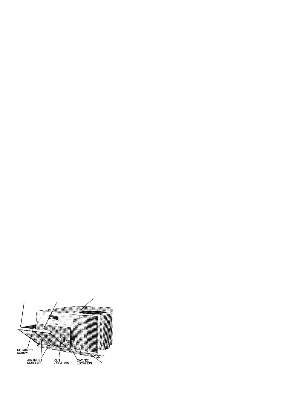
16. Slide outdoor air inlet screens in hood screen
tracks. Secure screens with screen retainer
across hood front. Secure screen retainer with
screw provided. See Fig. 22.
17. Replace upper filter access panel with screws
saved from step 2.
18. Turn base unit power on.
CLS
PINK
-O^Q-
PINK
-i
SEE NOTE
F
RED
_ OAT _
-
BLUE
CLS — Cooling Lockout Switch
EC — Enthalpy Control
OAT. — Outdoor Air Thermostat
NOTE; When Enthalpy Control (EC) is installed, outdoor air thermo
stat (OAT ) is removed from economizer
Fig. 21 — Wiring Connections for Outdoor
Air Thermostat/or Enthalpy Control
and Cooling Lockout Switch
AIR INLET SCREEN
RETAINER
OUTDOOR AIR
HOOD
BASE UNIT
: *
BASE RAIL
Fig. 22 — Economizer and Outdoor Air Hood
Assembled to Unit
START-UP
Unit Preparation — Make sure unit has been
installed in accordance with installation instruc
tions and applicable codes.
Compressor Mounting — Compressors are inter
nally spring mounted. Do not loosen or remove
compressor holddown bolts.
Internal Wiring — Check all electrical connections
in unit control boxes. . .tighten as required.
Refrigerant Service Valves — Eaeh unit system
has 2 Schrader type serviee ports, one on the suetion
line and one on the compressor discharge line. Be
sure that eaps on the ports are tight.
Crankcase Heater(s) are energized as long as there
is power to the unit. Energize heater(s) 24 hours
prior to base unit start-up.
Cooling — To start unit, turn on main power
supply. Set system selector switch to COOL and
fan switch at AUTO. Adjust thermostat to a setting
below room temperature. Compressor starts on
closure of contactor.
Check cooling effects at a setting above room
temperature. Cheek unit charge. Refer to Refrig
eration Charge in Service section.
Reset thermostat at a position above room tem
perature. Compressor will shut off.
TO SHUT OFF UNIT — Set system seleetor switch
at OFF position or reset thermostat at a position
above room temperature. Units are equipped with
Cyele-LOC™ proteetion device. Unit shuts down on
any safety trip, and indicator light on thermostat
comes on. Cheek reason for safety trip.
Compressor restart is accomplished by manual
reset at the thermostat by turning the seleetor switch
to OFF and then to ON.
Heating — To start unit, turn on main power
supply. Refer to Crankcase Heaters.
Set thermostat at HEAT and a setting above
room temperature, fan at AUTO.
First stage of thermostat energizes the first-stage
eleetric heater; seeond-stage electric heater elements
if installed. Cheek heating effeets at air supply
grille(s).
TO SHUT OFF UNIT — Set system selector switch
at OFF or set heating selector lever below room
temperature.
Ventilation {Continuous Fan) — Set fan and sys
tem selector switches at ON and OFF, respectively.
Evaporator air fan operates continuously to provide
constant air circulation.
Economizer Operation {50CD008) — See
pages 9 thru 12 for start-up and checkout proce
dures. If unit is equipped with modulating out
door air control (economizer), it should operate as
follows;
COOLING MODE — Evaporator and condenser
fans and compressor energize when there is a call
t
12