Carrier 50CD/CH User Manual
Page 7
Attention! The text in this document has been recognized automatically. To view the original document, you can use the "Original mode".
MANUAL
OUTDOOR
air
damper
assembly
L/NKA6E
ROD SETSCREW
#
a; . •W
LINKAGE ROD
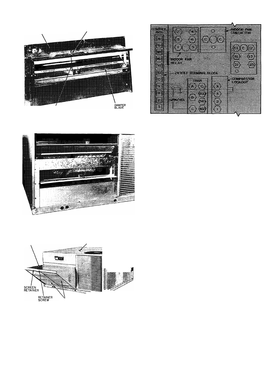
Fig. 7 — Damper Blade Adjustment
Fig. 10 — Control Box Details
m
Fig. 8 — Manual Outdoor Air Damper
HOOD
BASE UNIT
•>
^,r
AIR SCREENS
BASE RAIL
Fig. 9 — Outdoor Air Hood Assembled
to Base Unit (50 Series Shown)
Condenser Air Fan and Motor are factory set.
Refer to Service, Condenser Air Fan Adjustment,
as required.
Condensate Drain — See Fig. 3 and 4 for drain
location. A 7/8-in. ID preformed drain hose is
shipped clamped to the evaporator basepan. At
installation, reroute hose so that it passes thru the
hole in the evaporator basepan and the unit base
rail.
When installed properly, the hose protrudes thru
the base rail about 3in. on the 50CD008. On the
50CH008, hose protrudes thru the side of the base
rail about 1 inch.
Replace clamp over the hose where it passes thru
the basepan. This keeps the hose level. Use a trap at
least 4 in. deep and provide protection for trap
against freeze-up.
Field Power Supply — See Fig. 11 and Table 2.
Unit is factory wired for voltage shown on name
plate. On 208-volt installations, reconnect all trans
formers to 208- (200-) volt tap. Refer to unit label
diagrams. Pigtails are provided for field service on
units without electric heat (use factory-supplied
splices or UL-approved copper/aluminum con
nector). Units with electric heat are provided with
terminal block in single point box.
All field wiring must comply with National Elec
trical Code and local requirements.
Run power lines thru condenser coil end panel to
terminal connections as shown on unit wiring
diagram and in Fig. 3 and Fig. 4.
Operating voltage to compressor must be within
voltage range indicated on unit nameplate. On 3-
phase Units, voltages between phases must be
balanced within 2% and the current must be bal
anced within 10%.
Use the following formula to determine the %
voltage unbalance.
% Voltage Unbalance
_ max voltage deviation from average voltage
average voltage