Carrier 50CD/CH User Manual
Page 11
Attention! The text in this document has been recognized automatically. To view the original document, you can use the "Original mode".
BASE RAIL
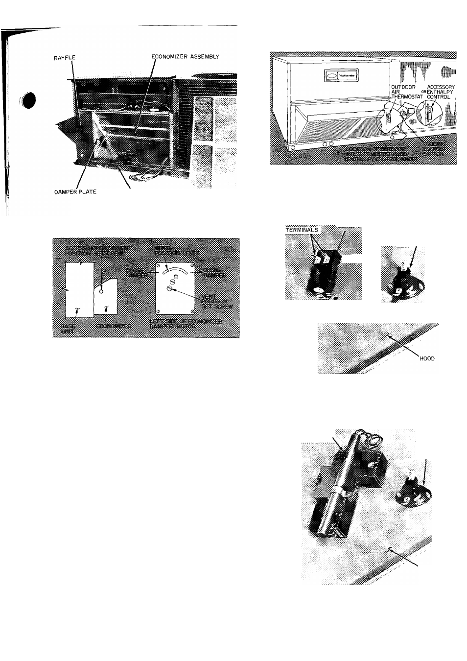
Fig. 18 — Baffle Installation Details
Fig. 19 — Vent Position Setting Details
:i OUTDOOR AIR THERMOSTAT
«(TERMINALS ARE UP)
: COOLING LOCKOUT
SWITCH
11. If vent air is not required, go on to step 12. If
vent air is required, proceed as follows:
a. Turn on base unit power. This energizes the
evaporator fan motor.
b. Slide economizer out of unit so that access
hole to vent position setscrew is visible. See
Fig. 19.
c. Adjust vent opening by loosening vent posi
tion setscrew on left side of economizer
damper motor and setting vent position
lever to adjust damper. See Fig. 19. Move
vent position lever back toward evaporator
coil to close damper or forward to open
damper. When adjustment is eompleted,
retighten setscrew.
d. Turn off base unit power and remove jumper
from red and black wires.
e. Slide economizer assembly back into unit.
12. Remove tape from outdoor air thermostat
(OAT.) and cooling lockout switch (CLS), and
fasten to inside of hood with screws and speed
clips provided. Make sure terminals on OAT.
are up. See Fig. 20.
1
ACCESSORY
: ENTHALPY,
CONTROL
cooling
LOCKOUT
SWITCH
HOOD
Fig. 20 — Outdoor Air Thermostat/
Enthalpy Control and Cooling Lockout
Switch Installation
11