Carrier 50CD/CH User Manual
Page 14
Attention! The text in this document has been recognized automatically. To view the original document, you can use the "Original mode".
Clean coil as follows:
1. Turn off unit power.
2. Remove top panel screws on condenser end of
unit. Remove screws from coil side of coil center
post. Do not remove center post.
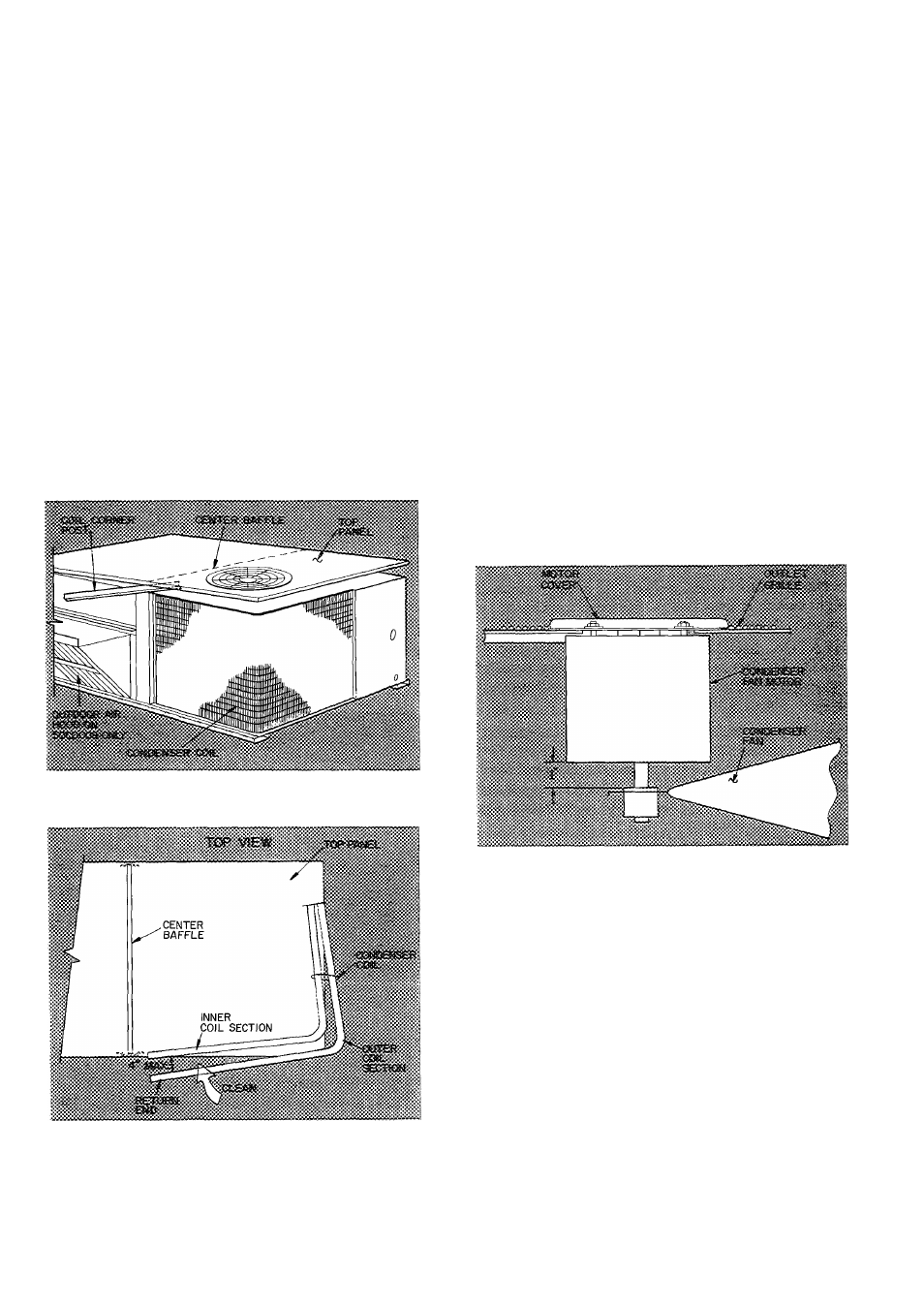
3. Remove condenser coil corner post. See Fig. 24.
To hold top panel open, place coil corner post
between top panel and center baffle. See Fig. 25.
4. Remove device holding coil sections together at
return end of condenser coil. Carefully separate
the outer coil section 3 to 4 in. from the inner coil
section. See Fig. 26.
5. Use a water hose or other suitable equipment to
flush down between the 2 coil sections to remove
dirt and debris. Clean the outer surfaces with
a stiff brush in the normal manner.
6. Reposition the outer coil section, remove the coil
corner post from between the top panel and
eenter baffle. Secure the sections together. Install
the corner post, coil center post and replace
all screws.
Fig. 25 — Propping Up Top Panel
CONDENSATE DRAIN — Check and clean each
year at start of cooling season. In winter, keep drain
and trap dry or protect against freeze-up.
FILTERS — Clean or replace at start of each heat
ing and cooling season, or more often if operating
conditions require it.
OUTDOOR AIR INLET SCREENS (50CD008) —
Clean screens with steam or hot water and a mild
detergent. Do not use throwaway filters in place of
screens.
Lubrication
COMPRESSORS — Each compressor is charged
with correct amount of oil at the factory.
LAN MOTOR BEARINGS — No lubrication of
condenser or evaporator fan motors is required
for first 5 years of operation.
Annually thereafter, clean and repack bearings
with a suitable bearing grease.
Condenser Air Fan Adjustment (Fig. 27) — Shut
off unit power supply. Remove condenser fan
assembly (grille, motor, motor cover and fan) and
loosen fan hub setscrews. Adjust fan height as
shown in Fig. 27. Tighten setscrews and replace
condenser fan assembly.
Fig. 26 — Separating Coil Sections
Fig. 27 — Condenser Air Fan Adjustment
Manual Outdoor Air Damper (50CD008) — If
outdoor air damper blade adjustment is required,
see Optional Manual Outdoor Air Damper section
on page 6.
Economizer Adjustment (50CD008) — Refer
to Economizer section under Installation.
Refrigerant Charge — Amount of refrigerant
charge is listed on unit nameplate (also refer to
Table 1). Refer to Carrier Standard Service Tech
niques Manual, Chapter 1, Refrigerants.
Unit panels must be in place when unit is oper
ating during charging procedure.
i
14