Carrier 50CD/CH User Manual
Page 8
Attention! The text in this document has been recognized automatically. To view the original document, you can use the "Original mode".
WITHOUT ELECTRIC HEAT
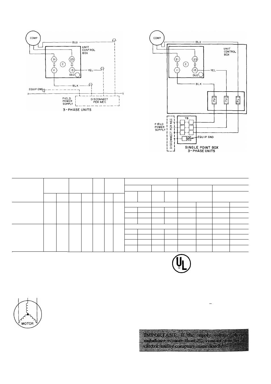
UNIT CONTROL BOX
WITH
ELECTRIC
HEAT
SINGLE POINT BOX
C — Contactor
Comp — Compressor
Gn*d*^ — Equipment Ground
. Factory Wiring
. Field Power Wiring
. Field Splice
Fu
TB
— Fuse
— Terminal Block
Fig. 11 — Field Power Wiring Connections
Table 2 — Electrical Data
50CD/CH008
NOMINAL
V-PH-HZ
VOLTAGE
RANGE
COMPR
OFM
IFM
ELECTRIC HEATERS
POWER SUPPLY
50CD008
50CH008
50CD008
50CH008
Kw
FLA
Kw
FLA
Min Ckt
j
MOCP
Arr
Min Ckt
j
MOCP
)ps
Min
Max
RLA
LRA
FLA
Hp
FLA
208/230-3-60
187
254
32
5
183
29
1
80
—
—
55/55
60
/
60
*
55/55
60
/
60
*
9
3
20-23
93
20-23
55/55
60/60
55/55
60/60
186
40-46
158
33-38
60/70
60/70
55/60
60/60
28
1
59-68
31
5
68-76
85/95
80/90
95/105
90/100
460-3-60
414
508
15
2
91
1
1
5
1
2
9
—
—
25
35
*
25
35
*
9
7
11
7
97
11
7
25
35
25
35
160
193
160
19
3
30
35
30
35
194
23
4
31
5
37
9
40
35
55
45
29
6
35
7
50
45
1
FLA
— Full Load Amps
Hp
— Horsepower
IFM
— Indoor Fan Motor
LRA
— Locked Rotor Amps
MOCP — Maximum Overcurrent Protection
OFM — Outdoor Fan Motor
RLA — Rated Load Amps
‘Fuse only
Example; Supply voltage is 460-3-60.
ABC AB = 452 volts
BC = 464 volts
AC = 455 volts
Average Voltage
452 + 464 + 455
1371
3
= 457
Determine maximum deviation from average
voltage:
(AB) 457 - 452 = 5 volts
(BC) 464 - 457 = 7 volts
(AC) 457 - 455 = 2 volts
Maximum deviation is 7 volts
Determine % voltage unbalance:
% Voltage Unbalance = 100 x
7
457
= 1.53%
This amount of phase unbalance is satisfactory
as it is below the maximum allowable 2%.
t