Carrier 50CD/CH User Manual
Page 6
Attention! The text in this document has been recognized automatically. To view the original document, you can use the "Original mode".
Outdoor Air Intake (50CD008) — The 50CD
can be equipped with an optional outdoor air
damper or an economizer that mixes outdoor air
with return air.
Field-Fabricated Ductwork
50CD — See Fig. 3. Secure all ducts to roof curb and
building structure before unit is placed on curb.
Do not connect ductwork to unit.
Cabinet return air static shall not exceed 0.35 in.
with economzier or 0.40 in. without economizer.
50CH — See Fig. 4. Secure all ductwork to flanges
on unit supply air and return air openings and
building structure.
50CD/CH — Insulate and weatherproof all ex
ternal ductwork, joints and roof/ wall openings with
flashing and mastic in accordance with applicable
codes. Insulate ducts passing thru an unconditioned
space and cover with a vapor barrier.
A minimum clearance is not required for any air
duct installation.
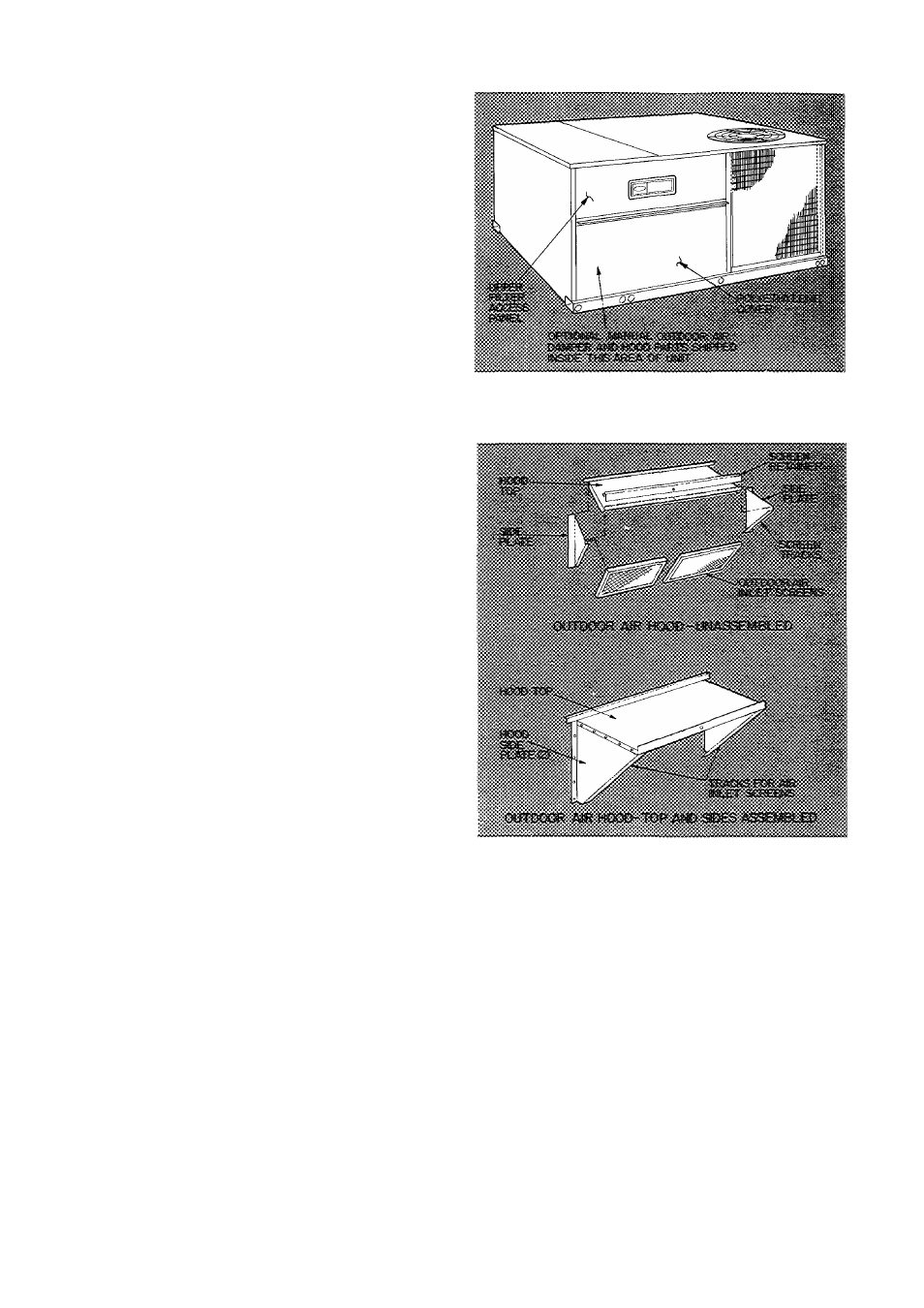
Optional Manual Outdoor Air Damper (50CD
008) — Optional outdoor air damper is shipped
with hood broken down in unit filter section.
See Fig. 5.
ASSEMBLY
1. Remove protective polyethylene cover from unit.
See Fig. 5.
2. Remove upper filter access panel (save screws).
See Fig. 5.
3. Remove hood parts from unit evaporator fan
and filter area. Assemble hood top and side
plates as shown in Fig. 6. Do not attach hood to
unit at this time.
4. Adjust outdoor air damper blade to desired
setting for outside air intake by releasing linkage
rod setscrew and adjusting linkage rod. See
Fig. 7. Secure damper blade in desired position
with setscrew.
5. Remove screws holding manual outdoor air
damper to unit. See Fig. 8.
Install outdoor air hood assembly, using screws
from step 5. These screws secure the manual
outdoor air damper assembly and the outdoor
air hood to unit. See Fig. 9.
Slide outdoor air inlet screens into screen tracks
on hood side plates. While holding screens in
place, fasten screen retainer to hood using screw
provided. Make sure bottom edge of screens rest
inside base rail as shown in Fig. 9.
Replace upper access panel with screws saved
from step 2.
9. To check percentage of ventilation air entering
unit, proceed as follows:
a. If unit power is on, turn it off.
b. Jumper red and black wires in 24-v barrier
in main control box. See Fig. 10.
c. Turn on unit power to energize evaporator
(indoor) fan.
6
.
7.
8
.
Fig. 5 — Access Panel Location
t
Fig. 6 — Outdoor Air Hood Details
d. Check percentage of ventilation air entering
unit. If percentage varies from that specified,
remove upper filter access panel and adjust
damper blade as described in step 4. Proce
dure may have to be repeated until proper
percentage of ventilation air is attained.
e. Turn off power. Remove jumper between
red and black wires.
f. Replace upper filter access panel.
50CH008 Unit Assembly — Remove packaging
and tape from evaporator fen drive system.
Evaporator Air Fan — Evaporator fan uses a belt-
drive motor which provides high static at nominal
airflow. The standard motor provides approxi
mately 0.95 in. static at nominal cfm and the alter
nate motor provides 1.0 in. static at nominal cfm.