Carrier 38GS User Manual
Page 8
Attention! The text in this document has been recognized automatically. To view the original document, you can use the "Original mode".
Low-Pressure Switch
is located on unit suction line
and resets automatically. Low-pressure switch set
tings are: cutout, 3 1 + 4 psig; cut-in, 60 (+ 15, - 0)
psig.
High-Pressure Switch
is located on unit liquid line
and resets automatically. High pressurestat settings
are; cutout, 425 ± 5 psig; cut-in, 320 ± 20 psig.
Crankcase Heater
warms compressor crankcase.
Prevents refrigerant dilution of oil in crankcase.
Outdoor Fan Thermostat
maintains proper con
densing temperature at high outdoor temperatures
by switching fan to high speed. Located in control
box (on 38CE).
Filter-Drier
is installed in liquid line.
Time Guard® Circuit
provides for a 5-minute delay
before restarting compressor after shutdown for
any reason. On normal start-up the Time Guard
timer causes a delay of 15 seconds after thermostat
closes before compressor will start. On compressor
shutdown, the timer recycles for 4 minutes, 45
seconds. During this time the compressor cannot
start.
Solid State Time Delay
provides for a 4-minute
delay before restarting compressor after shutdown
for any reason. On normal start-up, timer is
energized after thermostat closes and causes a
4-minute delay before compressor will start.
Compressor Protectibn Control System
(CPCS —
Solid State) provides; compressor motor locked
rotor protection; compressor start winding pro
tection; compressor motor running overload pro
tection; compressor overtemperature protection;
contactor antichatter protection.
The CPCS also provides for a 4- to 6-minute
delay before restarting compressor after shutdown
for any reason. I f compressor loading was light at
the moment compressor was shut off, the delay
will be approximately 4 minutes. If loading was
heavy, the delay will be approximately 6 minutes.
To troubleshoot the CPCS, use unit label diagram
or wiring booklet and the following Control Circuit
Troubleshooting Chart.
CONTROL
CIRCUIT
TROUBLESHOOTING
CHART NOTES:
CAUTiON: Iks
nmt
i>ece|siacle fiHscomsctsd fr«i
ebm*
will up CICS
1. Ensure thermostat calls for cooling before
troubleshooting unit.
3.
4.
5.
6
.
2. To disconnect plug from receptacle on CPCS
board — press in tabs located on the receptacle
and pull plug gently while holding tabs. Do not
pull on wiring.
When performing troubleshooting checks, CPCS
receptacle must be plugged into CPCS board.
Receptacle female connections, which do not
grip the male pin tightly, may be repaired with
a small pen knife.
When taking meter readings at CPCS receptacle,
bottom meter probe into terminal hole to
ensure good electrical contact.
Replace CPCS board if electrical short circuit
causes compressor failure. An electrical short in
compressor can short the triac (electronic
switch located on CPCS board). Triac may fail
in a closed (conducting) position and will not
open the control circuit.
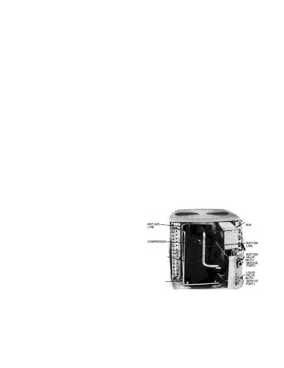
Compressor Removal
(See Table 7 for compressor
information and Fig. 5 for component location.)
1. Shut off power to unit. Vent refrigerant to
atmosphere or use refrigerant removal methods
shown in Carrier Standard Service Techniques
Manual, Chapter 1.
Remove top access cover and rear access wrap
per (Fig. 5).
Remove power leads from compressor terminal
box. Unsweat suction and hot gas lines.
Remove compressor hold-down bolts. Lift
compressor out thru top or back of unit.
2
.
3.
4.
CONTROL
COMPRESSOR
TERMINAL
BOX
LIQUID LINE
Fig. 5 — Condensing Unit with Access
Panels Removed
(38CE Unit Shown)