Carrier 38GS User Manual
Air-cooled condensing units
Attention! The text in this document has been recognized automatically. To view the original document, you can use the "Original mode".
Number One
Airconditioning
Mater
Syracuse New York
Air-Cooled Condensing Units
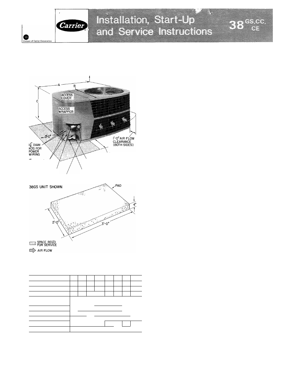
4'-0" OVERHEAD SPACE REQ'D
FOR SERVICE AND AIR FLOW
g DIAM KOS FOR
CONTROL WIRING
SUCTION LINE CONN
3 -0 (BOTH SIDES)
LIQUID LINE VALVE
LIQUID LINE CONN
SUCTION LINE
VALVE
CONCRETE
MOUNTING
Fig. 1 — Dimensions, Connections and Mounting Pad
38GS,CC,CE Unit
Table 1 — Installation Data
38GS
014 018 024 030
036 042 048 060t
COND UNIT 38CC
-
-
-
030
036 042 048 060t
38CB
-
-
-
002*
003 004 045 005
OPER WT (lb)
130
135
142|149
158
191
193
200
UNIT DIM. (ft-in.)
Length A
2-10V4
---- -----
Width B
'l-4
1-10
Height G
1-4
N4
Com
1-4 1 1-4 (2-0
2-0
2-0
REFRIG CONN.(in.)
DOtibl
e Fittings
Suction (ODF)
%
l Y s T
'/
b
I
%
'/4t
Liquid (ODF)
'8
*5/8-in suction connection on 38CE002
t38CE045,005 and 38GS.CC060 are factory supplied with 3/4- to
1
1/8-in
suction
valve
adapter
(field
installed)
for
1
1/8-in
suction line
TRANSPORTATION DAMAGE
File claim with shipping company if shipment is
damaged or incomplete.
Unpackaging Unit
— Move condensing unit to final
location. Open carton at end marked “compressor
end.” Slide unit from carton taking special care to
not damage service valves or grilles.
PRELIMINARY SURVEY
Consult local building codes and National
Electrical Code (NEC) for special installation
requirements.
When installing unit, allow sufficient space for
air flow clearance, wiring, refrigerant piping and
servicing unit. Position unit so water from roof or
eaves does not flow directly on top of unit.
Install unit on a solid, level mounting pad. Unit
can be attached to pad with a mastic adhesive or
by drilling holes in base pan for 1/4-in. mounting
bolts. Do not block base pan water drainage holes.
38GS,CC,CE
Condensing
Units
Connected to
Carrier Matched Evaporators with Carrier Acces
sory Tubing
— Check system refrigerant charge
when tubing lengths are above or below 25 feet.
See Refrigerant Charging (page 10) for details.
38GS,CC,CE Condensing Units Connected to Non-
Carrier Evaporators
— Check refrigerant charge
when condensing unit is added to a system in
which other than a Carrier approved evaporator is
being used or where the evaporator has been
previously installed. Field-supplied refrigerant pip
ing must be in accordance with Field-Supplied
Piping Data, Table 3.
Where indicated on Table 3 for 38GS,CE units,
install a liquid line filter-drier and accessory crank
case heater on condensing unit. (Filter-drier is
factory supplied on CE045,005 units.) Accessory
start capacitor and relay also required on 38GS
units, but not normally required on 38CE units.
See Compressor Service (page 7). All above items
are standard or not required for 38CC units.
Use an evaporator coil with a bleed-type ex
pansion device. If coil does not have a bleed-type
expansion device it may be necessary to add an
accessory start capacitor and relay to condensing
unit. This would require removing compressor start
thermistor (PTC device) on units so equipped.
© Carrier Corporation 1975
Form 38GS-13SI
Document Outline
- Number One
- Airconditioning
- Mater
- Air-Cooled Condensing Units
- Fig. 1 — Dimensions, Connections and Mounting Pad 38GS,CC,CE Unit
- TRANSPORTATION DAMAGE
- PRELIMINARY SURVEY
- PIPING CONNECTIONS
- ELECTRICAL DATA AND WIRING
- of ifolt ois tmpro|>er Ime
- Install a Branch Circuit Fused Disconnect of
- Fig. 4 -- Control Circuit Connections
- START-UP INSTRUCTIONS
- Start Procedure
- COMPRESSOR SERVICE
- UNIT PROTECTION
- CONTROL CIRCUIT TROUBLESHOOTING CHART (GS,CC048 and 060)
- PUMPDOWN PROCEDURE
- REFRIGERANT CHARGING
- Table 8 — Refrigerant Charging Methods (Carrier Approved Systems)
- CAIHIOI^; Do myi tmé