Caihioi^; do myi tmé – Carrier 38GS User Manual
Page 11
Attention! The text in this document has been recognized automatically. To view the original document, you can use the "Original mode".
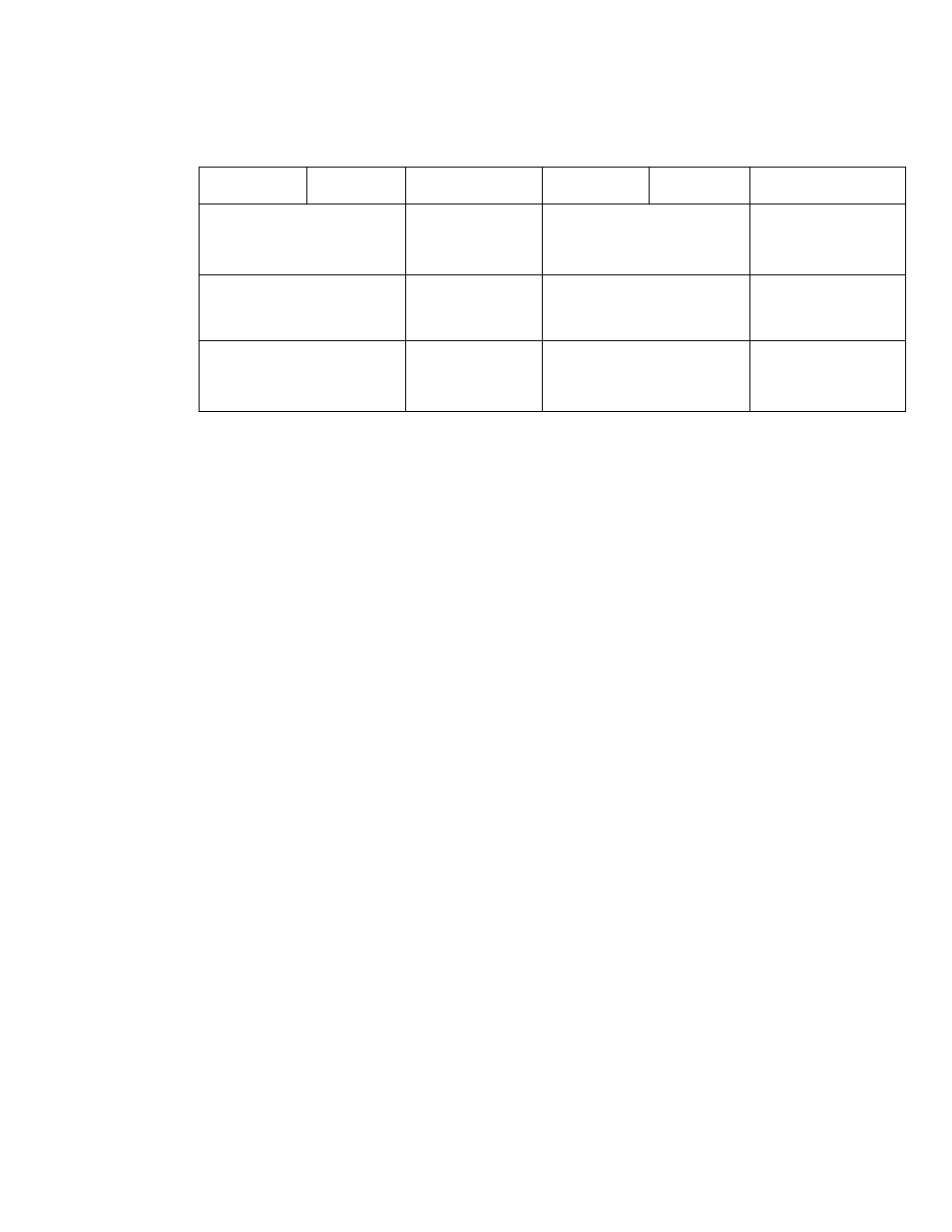
Table 8 — Refrigerant Charging Methods
(Carrier Approved Systems)
CONO
UNIT
38GS
38CC
38CE
METHODS OF CHECKING
0^ ADJUSTING CHARGE
System Refrigerant Control
RECHARGING METHODS
System Refrigerant Control
AccuRater^ ^
Capillary
Tube
TXV
AccuRater
Capillary
Tube
TXV
Chargemaster ®
or
Charging Chart
Charging Chart
Weight Method
plus
Chargemaster or
Charging Chart
Wei ght Method
plus
Charging Chart
Chargemaster
or
Charging Chart
Charging Chart
or
Sight Glass
Wei ght Method
plus
Chargemaster or
Charging Chart
Weight Method
plus
Charging Chart or
Sight Glass
Chargemaster
or
Charging Chart
Charging Chart
Weight Method
plus
Chargemaster or
Charging Chart
Wei ght Method
plus
Charging Chart
TXV
— Thermal Expansion Valve
Charging Chart Method
— For thermal expansion
valve systems, use Charging Chart, Fig. 6 or 7. See
Carrier Standard Service Techniques Manual,
Chapter 1, for procedure. For capillary tube or
AccuRater"''i'^ systems, use Charging Chart, Fig. 8
or 9 and the following procedure:
1. Operate unit a minimum of 10 minutes before
checking charge.
2. Measure suction pressure by attaching a gage to
suction valve service port.
3. Measure suction line temperature by attaching a
service thermometer to unit suction line near
compressor. (Insulate thermometer for accurate
readings.)
4. Measure outdoor (condenser inlet) air dry-bulb
temperature with second thermometer.
5. Refer to Charging Chart (Fig. 8 or 9). Find
condenser air temperature and project hori
zontally to curve showing suction pressure.
6. From intersect point, project vertically down
ward to chart suction hne temperature.
7. If unit has a higher suction line temperature
than chart, add refrigerant until chart tempera
ture is reached.
8. If unit has a lower suction line temperature
than chart, bleed refrigerant until chart tem
perature is reached.
9.
If condenser inlet air temperature or unit
suction pressure changes, change to new suction
line temperature on chart.
Chargemaster® Operation
— Operate unit 10 min
utes before using Chargemaster (Carrier Part No.
38GC680004).
1. Tape Chargemaster feeler bulb to suction line
close to condensing unit. Insulate bulb. Ensure
suction line is clean for good contact with bulb.
2. Connect refrigerant drum to Chargemaster inlet
port with drum in position for vapor charging.
3. Connect Chargemaster outlet port to unit suc
tion valve service port.
4. Crack valves on refrigerant drum and Charge-
master to purge lines from drum to suction
valve. After purging lines, close valve on Charge-
master only.
5. Measure outdoor air dry-bulb temperature.
6. Crack unit suction valve and read evaporator
temperature at red needle position on Charge-
master temperature gage and suction line tem
perature at black needle position.
CAIHIOI^; Do myi tmé
7. Enter Chargemaster Charging Chart, Table 9 or
10, at outdoor air temperature (step 5) and
evaporator temperature (step 6). Find the
suction line temperature required for correct
system charge. If actual suction line tempera
ture (step 6) is higher than table value, the
system is undercharged. If suction line tempera
ture is lower than table value, the system is
overcharged.
Example (Table 10): At outdoor air tempera
ture of 85 F and evaporator temperature of
44 F, the system will be correctly charged at
71 F ± 2 F suction line temperature.
1 1