Start-up instructions, Start procedure, Fi-lb lorquc »hen – Carrier 38GS User Manual
Page 6
Attention! The text in this document has been recognized automatically. To view the original document, you can use the "Original mode".
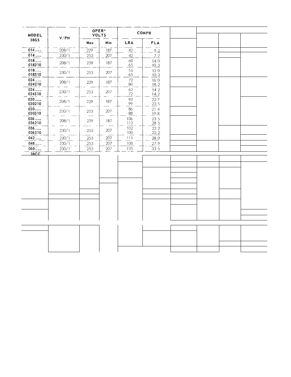
Table 4 — Electrical Data
FAN
BRANCH CIRCUIT
Wire
Sizef
(AWG)
Max
Ft
Wiref
Fusei
Amps
FLA
2.4
14
40
20
2.1
14
33
20
2 4
12
28
30
2,4.........
___12______
..37..........
20
2 1
12
36
25
2.1
14
19
25
2 4
10
40
35
2.4
10
35
40
2 1
12
31
30
2.1
12
31
30
2 4
8
45
50
2.4
8
45
50
2 1
10
34
30
2.1
10
36
45
2 4
8
44
55
2.4
8
36
65
2 1
10
33
50
2.1
10
33
50
2.1
8
41
65
2.1
8
42
55
2 1
6
54
75
030___
200/230/3
253
180
70/60
13 0/11 5
2 0/2 .0
12
49
30/25
036___
200/230/3
253
180
80/70
14 0/12 6
2 0/2 0
12
45
30/30
036___
460/3
506
414
35
6 5
1.0
14
91
15
042___
200/3
220
180
92
17 0
2 0
10
49
35
042___
230/3
253
207
92
15 8
2 0
10
58
35
042___
460/3
506
414
46
7 8
1 0
14
100
15
048___
200/3
220
180
90
18 6
2 0
10
46
40
048___
230/3
253
207
78.5
16.1
2.0
10
60
35
048___
460/3
506
414
39 3
8 3
1 0
14
100
20
060___
200/3
220
180
n o
23 0
2.0
8
'■ 67
50
060___
230/3
253
207
100
20 5
2 0
10
47
45
060___
460/3
506
414
50
10 3
1 0
1 4
1 74
20
38CE
002___
230/1
253
207
65
10.3
2-.1
12
42
25
003___
230/1
253
207
82
16 8
2 1
10
42
35
004___
230/1
253
207
~88
19.8
2.1
10
36
45
045___
230/1
253
207
88
23.9
2.1
10
31
55
005___
230/1
253
207
100
27.9
2 1
8
42
60
FLA
— Full Load Amps
LRA
— Locked Rotor Amps
______Electrical data shown applicable to all units for
which complete model number is not shown
•Permissible limits of the voltage range at which the units
will operate satisfactorily
(■Copper wire sizes Aluminum field wiring may be used when splice-
connected to copper pigtails from unit with factory-supplied wire nuts
Use latest National Electrical Code for aluminum wire sizing
^Maximum dual element fuse size
NOTE Control circuit voltage is 24 volts on all units
START-UP INSTRUCTIONS
If unit is equipped with crankcase heater,
energize heater a minimum of 24 hours before
starting unit To energize heater only, set thermo
stat at “Off” position and close electrical dis
connect to condensing unit.
Units with Time Guard® circuit or solid state
time-delay may not start for approximately 4 to 5
minutes after thermostat closes. See compressor
controls, pages 7 and 8.
Start Procedure
1. Backseat (open) liquid and suction line service
valves.
4 Do exscod
iighiiiiing.
ov«rtii^i
6
fi-lb lorquc »hen
2. Set thermostat selector switch at "Off.”
3. Set room thermostat at desired temperature.
4. Close electrical disconnects energizing entire
system.
5. Set room thermostat at “Cool” and fan switch
as desired (“Fan”) (“Auto.”).
Check system refrigerant charge. See Refrig
erant Charging.
Motors and controls will operate satisfactorily
in a range from 10% above to 10% below nominal
unit voltage (Table 4).