Electrical data and wiring, Of ifolt ois tmpro|>er ime, Install a branch circuit fused disconnect of – Carrier 38GS User Manual
Page 4
Attention! The text in this document has been recognized automatically. To view the original document, you can use the "Original mode".
c
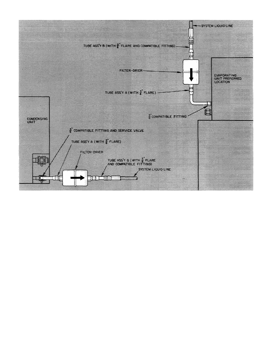
Fig. 2 — Filter-Drier Assembly Installation (38CC, 38CE045 and 005)
SWEAT CONNECTION (Use refrigerant grade
tubing.)
1.
Remove locking nut, rubber 0-ring and
Schrader core from valve.
2. Cut tubing to correct length.
3. Insert tube into Compatible Fitting. Wrap top
and bottom of service valves in wet cloth to
prevent damage by heat. Solder with low
temperature (450 F) silver alloy solder.
4. Replace Schrader core.
5. Evacuate or purge system with field-supplied
refrigerant.
ELECTRICAL DATA AND WIRING
Field wiring must comply with local and
national fire, safety and electrical codes. Voltage to
unit must be within ± 10% of voltage indicated on
nameplate. Contact local power company for
correction of improper line voltage.
of ifolt ois tmpro|>er Ime
When making electrical connections, provide
clearance at unit for refrigerant piping connections.
See Table 4 for recommended wire and fuse sizes.
Install a Branch Circuit Fused Disconnect
of
adequate size to handle unit starting current.
Locate disconnect within sight of and readily
accessible from the unit, per section 440-14 of
National Electrical Code (NEC).
Bring Line Power Leads Into Unit
— Extend leads
from fused disconnect thru hole provided in service
embossment (Fig. 1) and thru 7/8-in. hole into
control box.
Connect Ground Lead to a Ground Lug in Control
Box
for safety. Connect power wiring. See Fig. 3.
Splice line power leads to red and violet pigtails on
38GS,CE units or to yellow pigtails (3) on 38CC
units. Use wire nuts supplied with unit. Tape each
connection. Wire nuts are suitable for copper or
aluminum wire since they contain joint compound.
Control Power
(24 v) wiring is brought thru hole in
service embossment and spliced to yellow pigtails
on all units. See Fig. 4.
Furnace or fan-coil transformer must be used as
24-v supply for system as shown in Fig. 4 (At least
a 40-va transformer is recommended.) Current
38GS048,060 and 38CC048,060 units are equip
ped with a low-voltage transformer used to power
contactor thru unit control circuit. This trans
former must not be used for powering the indoor
thermostat control circuit.