Piping connections, Hh0iad042 – Carrier 38GS User Manual
Page 2
Attention! The text in this document has been recognized automatically. To view the original document, you can use the "Original mode".
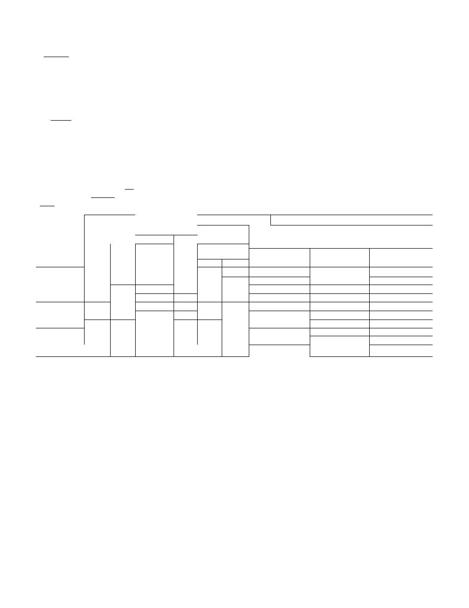
Table 2 — Accessories
PART
NUMBER
HH01AD040
HH93AZ040
JHH51AR00J[^
HH07AT070,
HH07AT074
H N93^076
HH0iAD042”
HH93AZ042
HH01YA092
HH_93_YZ094
32LT900301
(200-3 Ph)
32LT900601
(460-3 Ph)
38GS900102
38GS900212
38GS900112
38GS900292
38GS900172
DESCRIPTION
Low-Voltage
Control
—
Honeywell
Deluxe
Thermostat
Thermostat Subbase
Comfort Control Center (Use with HH01AD040)
Low-Voltage Control — Honeywell Thermostat
Thermostat Subbase (with Automatic Changeover)
Low-Voltage
Control
~
Honeywell
Thermostat
Thermostat Subbase
Low-Voltage
Control
—
Grayson
Thermostat
Thermostat Subbase
Solid State Head Pressure Control
Indoor Fan Relays (^¡x HN61KJ210)
40VA Low-Voltage Control Transformers
(24 V - Six 38GS900Q9])
Crankcase Heaters (Six 38GS900131)
Crankcase Heaters (Six 38GS900281)
Start Capacitor and Relay Package (Six 38GS900041)
USAGE
38GS,CC,CE
38CC — (Fan motor suitable for 32LT)
38GS,CC,CE
38GS,CC,CE
38GS (except 38G5014), 38CE
38GS0Ì4
38GS (except 38GSÒ42), 38CE
38GS900182
Start Capacitor
and Relay F^ackage
(Six 38GS900051
38GS042
Tubing Pa ckages
Liqui d
Suction*
UNIT
T ube
OD
Fnd
Lgth
(ft)
OD
(in.)
Tube End
OD (in.)
OD
(in.)
in.)
38GS
38CC
38CE
Evap
Cond
38GC900031
10
%
^8
%
^41
I
V4
014,018,024
-
002
38GC900071
10
r 5/^
^8
%
3/
H
/4
030,036,042,048
030,036,042,048
003,004,045,005
38GC900041
18
%
y« ,
^8
% t
V
/8
014,018,024
-
002
38GC900081
18
%
%
% 1
%
%
030,036,042,048
030,036,042,048
003,004,045,005
38GS900221
25
% :
%
^8
% t
%
014,018,024
-
002
38GC900091
25
%
%
%
%
^/4
030,036,042,048
030,036,042,048
“0Ü3%O470457O0r^
38GC900061
35
V
D6
%
%
% t
=/8
014,018,024
-
002
38GC900101
35
V
V
/4
%
V
/4
030,036,042,048
030,036,042,048
003,004,045,005
38GC900191
50
%
%
I V4t
%
014,018,024
-
002
38GC900ni
50
V
4
%
%
y —
/4
k4
030,036,042,048
030,036,042,048
003,004,045,005
*AII suction lines have a 90° bend at one end
tForb/8-in evaporator connection, cut off 3/4-in end
PIPING CONNECTIONS
Condensing units can be connected to evap
orator sections using Carrier accessory tubing
package or field-supplied tubing of refrigerant
grade.
(Accessory
tubing
not
available
for
38GS060, 38CC060.) See Table 2 for accessory
tubing sizes and Table 3 for recommended field-
supplied tubing sizes. Where evaporator is 20 ft or
more below condensing unit, reduce liquid line size
one diameter (min 1/4-in. OD).
A capacity reduction will result if accessory
tubing is used in 38CE045,005 systems. For
example, when a 25 ft accessory tubing package is
used, there will be a capacity reduction of 3 3/4%
on 38CE045 and 5% on 38CE005 systems. For
maximum capacity from these systems, use tubing
sizes shown in Table 3.
When other than 25 ft of interconnecting
tubing is used, follow special requirements de
scribed in Refrigerant Charging. Do not use less
than 10 ft of liquid line. Do not cut 5/16-in. or
1/4-in. liquid line. Bend or coil to fit.
Do not use damaged or contaminated tubing. If
accessory tubing package or evaporator section has
been open for more than 15 seconds per connec
tion, evacuate or purge evaporator coil and tubing
system (use field-supplied refrigerant, not unit
refrigerant). Always evacuate or purge if field-
supplied tubing is used.
Before Connecting Unit Piping,
consider the
following:
38CE045,005 AND 38CC UNITS - A filter-drier
package is shipped with these units. Included with
filter-drier are 2 short length tubing assemblies that
are equipped with flare and/or Compatible Fit
tings. Use tubing assemblies to install filter-drier
into system liquid line at evaporator or condensing
unit. See Fig. 2. Connect tubing assembly A (90°
assembly) to evaporator or condensing unit liquid
line Compatible Fitting. Complete the filter-drier
installation as shown.