Carrier 38GS User Manual
Page 3
Attention! The text in this document has been recognized automatically. To view the original document, you can use the "Original mode".
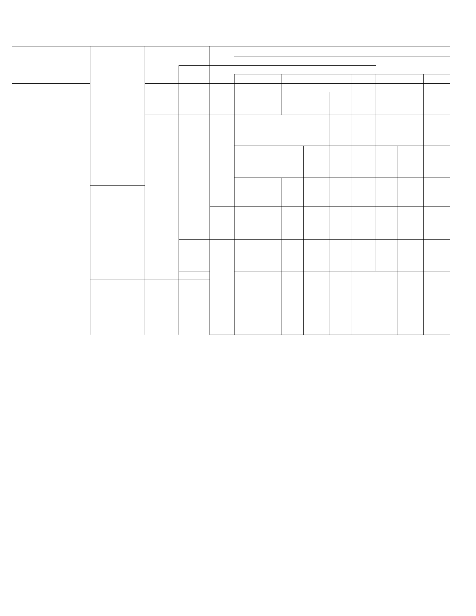
Table 3 — Field-Supplied Piping Data
MAX COND
REFRIGERANT LINE LENGTH (ft)
COND
REFRIG
UNIT HT (ft)
25- 50 51»
7S
7&~
1
m
f 3 UNIT
CONTROL
Above
Be low
Line Diameter (in* OD)
X-
Evap
Evap
Suet
Liq
iÄiii
Litj 1
LE
íj
TXV
90
90
'
38GS014,
38GS018
Cap. Tube
or
AccuRater'*'^
150
50
V
'8
V»
'x
iiiiii
lili
IH
iiiiii
¡Mil
38GS024
TXV
Cap. Tube
yo
150
90
50
%
%
IIBI
■
AccuRater
38GS030,
38CC030,
38CE002
Cap. Tube
or
AccuRater
150
__
50
%
Vs
iiiiiiiiiii
wmmmmmmm
ilM
MB
ilBi
%
38GS036,
38CC036,
38CE003
TXV
90
90
Cap. Tube
or
AccuRater
150
50
%
V» T
ISl
38GS042,
38CC042,
38CE004
TXV
90
90
Cap Tube
or
AccuRater
150
50
/4
V»
N
s
TXV
90 ■
90
38GS048,
38CC048
Cap Tube
or
AccuRater
150
50
%
% liM
T
%
■
TXV
90
90
38CE045
Cap. Tube
or
150
50
1%
% Iliiii
k
V
11
»
AccuRater
Äiii
38GS06 0,
38CC060,
38CE005
L^y
Cap. Tube
or
AccuRater
90
150
90
50
IV»
V»
*
Í...............
Cap. Tube
TXV
Crankcase heater and liquid line filter-drier required
on 38GS and 38CE units Accessory start capacitor
with
relay
also
required
on
38GS
unit,
but
not
normally
required
on
38CE
units
See
Compressor
Service Reduce liquid line diameter by 1/8-in OD
(min 1/4-in OD) when evaporator is 20 ft or more
below condensing unit
■ Capillary Tube
- Thermal Expansion Valve
NOTES
1 The following system modifications are required adjust
refrigerant charge on systems with over 25 ft separation
between
condensing
unit
and
evaporator
(See
Refrigerant
Charging ) Adjust system oil charge as described in Note 2
Oil
charge
adjustment
add
1%
of
nominal
oil
charge
in
system (Table 7) for each 10 ft of refrigerant line length
above 50 feet Eor example, a system that has a 50-oz oil
charge with 1 50 ft of interconnecting piping requires 5 oz of
additional oil as shown below:
150 ft - 50 ft = 100 ft
100 ft -E 10 ft = 10 ft
1 0 x 1 % = 1 0 % ( 1 0 )
10
X
50 oz = 5 oz
Do not permit condensing unit to short cycle, particularly on
applications
with
long
vertical
line
lengths
Correct
short
cycling condition immediately
Connection Procedure
— When making tubing
connections, be sure to provide clearance at unit
for electrical connections.
Connect refrigerant liquid and suction lines to
condensing unit, Fig. 1. Unit Compatible Fittings
permit 2 methods of refrigerant line connection;
mechanical (quick connect) or sweat connection.
Make suction line connection first.
38CE045,005, 38GS060 AND 38CC060 UNITS -
Remove suction line adapter taped to compressor
suction line. Connect 3/4-in. end of adapter to unit
suction line Compatible Fitting. Sweat connect
refrigerant suction line to 1 1/8-in. end of adapter.
Connect liquid refrigerant line to unit.
MECHANICAL CONNECTION (Mate one set of
connections at a time.)
1. Loosen nut on Compatible Fitting one turn. Do
not remove.
Remove plug and be sure 0-ring is in the groove
inside the Compatible Fitting.
Cut tubing to correct length.
Use gage on tag attached to service valve to
mark tube end for correct insertion depth.
Insert tube into Compatible Fitting until it
bottoms. (Tube should be inserted at least as
far as mark on tubing.)
Tighten nut until it bottoms on back coupling
flange.
2
.
3.
4.
5.