Carrier 38AH024-034 User Manual
Page 3
Attention! The text in this document has been recognized automatically. To view the original document, you can use the "Original mode".
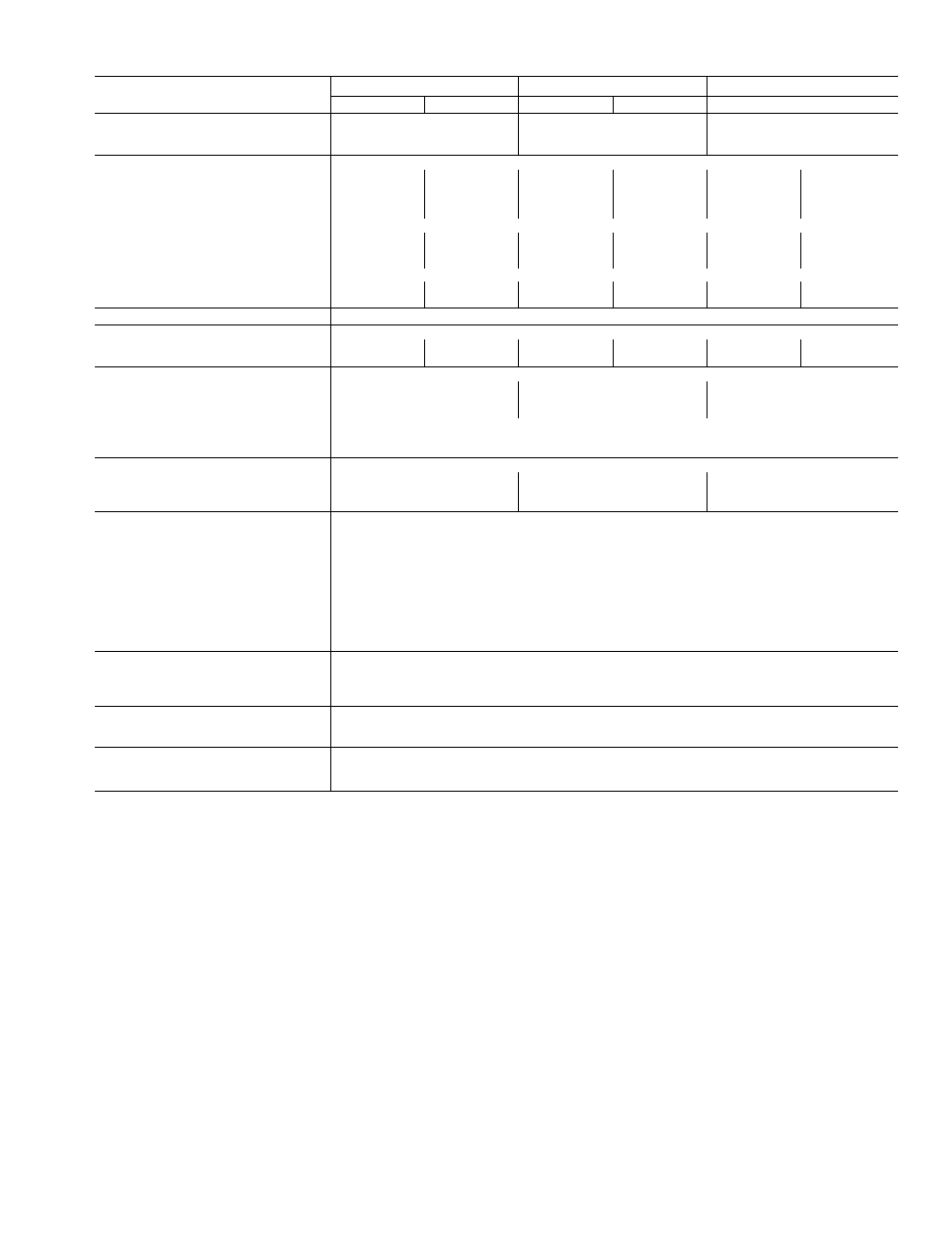
Table 1A — Physical Data — English
UNIT 38AH
024
028
034
Circuit 1
Circuit 2
Circuit 1
Circuit 2
Circuit 1
Circuit 2
OPERATING WEIGHT (lb)
With Alurninum-FIn Coil
1760
1820
1880
With Copper-Fin Coil
1923
1982
2097
COMPRESSOR
Reciprocating Semi-Hermetic
Type
06DH824
06DA824
06DH328
06DA328
06DH328
06DA537
Quantity Cylinders (ea)
6
6
6
6
6
6
Speed (rpm) — 60 Hz
1750
1750
1750
1750
1750
1750
- 50 Hz
1450
1450
1450
1450
1450
1450
Capacity Steps
(FIOP or Асу) - %
100
100
100
100
100
100
- %
66*
__
66*
—
66*
—
- %
33t
—
33t
—
33t
—
Unloader Setting (psig)
Factory Installed
— Load
76
—
76
—
76
—
— Unload
58
—
58
—
58
—
OIL CHARGE PER CIRCUIT (Pt)
10
REFRIGERANT, TYPE**
R-22
Shipping Charge (lb)
3
3
3
3
3
3
Operating Charge, Typical (lb)
20
20
20
20
25
25
CONDENSER FANS
Propeller Type — Direct Driven
Quantity...Dia (in.)
2.. 30
2
30
2. .30
Nominal Hp
1 0
1 0
1.0
Nominal Airflow (cfm)
16,700
16,700
15,700
Speed (rpm) — 60 Hz
1140
- 50 Hz
950
Watts (ea) - 50/60 Hz
1550
CONDENSER COIL
Enhanced Copper Tubes, Aluminum Lanced Fin
Rows...Fins/in.
2.. 19
2
19
3.. 17
Total Face Area (sq ft)
39 20
39 20
39.20
Storage Cap. (Ib)tt
37 7
37.7
56.6
CONTROLS
Pressurestat (psig)
High Pressure
Cutout
426 ± 7
Cut-in
320 ± 20
Low Pressure
Cutout
27 ± 3
Cut-in
44 ± 5
Oil Pressure
Manual Reset
Cutout (Diff)
60
Cut-in (Diff)
8.8
FAN CYCLING CONTROLS
No. 2 Fan:
Temp Close (F)
70 ± 3
Temp Open (F)
60 ± 3
PRESSURE RELIEF
Fusible Plug
Location
Liquid Line, Suction Line, Compressor
Temp (F)
210
CONNECTIONS (Sweat) (ea ckt)
Suction — in. OD
1%
Liquid — in. OD
%
LEGEND
Diff — Differential
FlOP — Factory-Installed Option
VAV — Variable Air Volume
'Standard unit — single suction pressure-actuated unioader on compressor no 1
tVAV FiOP — doubie eiectrically actuated unloaders on compressor no 1
"With 25 ft of interconnecting piping
ttCondenser 80% full of liquid R-22 at 120 F