Carrier 38AH024-034 User Manual
Page 13
Attention! The text in this document has been recognized automatically. To view the original document, you can use the "Original mode".
(
"
AFR
___
Airflow Relay
LLSV
—
AFS
—
Airflow Switch
LOR
—
C
—
Contactor, Compressor
LPS
—
CB
—
Circuit Breaker
OPS
—
CLO
—
Compressor Lock-Cut
PL
—
COM
—
Common
SOLR
—
COTP
—
Compressor Cvercurrent Protection
STAT
—
CR
—
Control Relay
TB
—
DISC
—
Disconnect
TGD
—
HPS
—
High-Pressure Switch
TRAN
—
IPC
—
Indoor-Fan Contactor
U
—
IPR
—
Indoor-Fan Relay
VA
—
kcmil
___
thousand circular mils
VAV
—
LLS
-
Liquid Line Solenoid
Liquid Line Soienoid Valve
I
I
Lock-Out Reiay
---------
Low-Pressure Switch
^
>
Oii Pressure Switch
Plug Assembly
O
Solenoid Relay
__^
Thermostat
______
Terminal Block
______
Time Guard® Device
Transformer
Unloader (Solenoid)
______
Volt-Ampere
Variable Air Volume
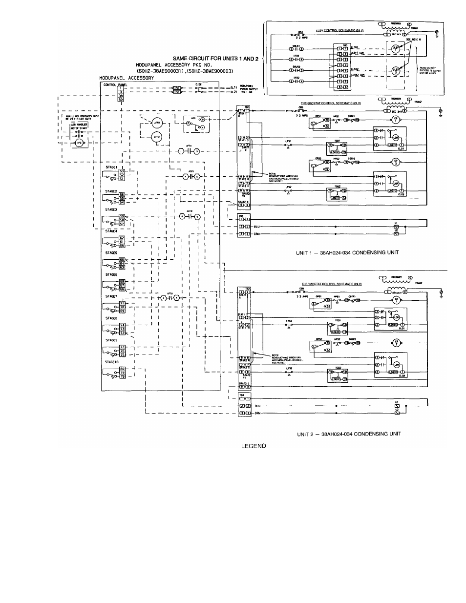
Fig. 10 — Typical Wiring Schematic — VAV ModuPaner
Two Dual-Circuit Condensing Units
with Air Handler
Terminal Block Connection
Marked Terminal
Unmarked Terminal
Unmarked Splice
Field Accessory Wiring
Factory Wiring
Field Control Wiring
Field Power Wiring
Indicates Common Potential,
Does Not Represent Wiring
13